SAAB 9000. Manual — part 42

9•18 Braking system
20.21 Rear wheel ABS sensor (arrowed)
20 Extract the sensor cable from the clip, and
carefully guide the connector through the
grommet in the wheelarch.
21 Slacken and withdraw the sensor retaining
bolt (see illustration), then extract the sensor
from the hub assembly.
Rear wheel sensors - refitting
22 Push the sensor into the drilling in the hub
assembly, then refit and tighten the retaining
bolt.
23 Using a feeler blade inserted between the
sensor tip and the toothed disc, set the
clearance to the value listed in Specifications.
When the clearance is correct, tighten the set
screw.
24 Refit the remainder of the components by
reversing the removal sequence.
Rear wheel sensors (later type) -
retro-fitting to pre-1990 models
Note: Vehicles from 1990 model year onwards
are fitted with a different type of wheel sensor
and toothed disc. The sensors can be retro-
fitted to pre-1990 model year cars, as follows.
25 Slide the adjusting sleeve off the old
sensor, after slackening the set screw.
26 If renewing the fibre spacer on a used
sensor, ensure that all traces of the old spacer
are removed, using a fine wire brush and a rag
moistened with a suitable solvent. Once the tip
of the sensor is clean, peel the backing film
from the rear of the new 0.65 mm thick fibre
spacer, and press it onto the tip.
27 Slowly turn the brake disc by hand, and
using a fine wire brush, clean off any traces of
dirt and old fibre spacer from the toothed disc.
28 Insert the sensor into the drilling in the hub
assembly, and tighten the retaining bolt.
Gently push the spacer against the surface of
the toothed disc, and tighten the set screw.
Caution: Do not rotate the
toothed disc until the sensor has
been secured in position, or the
disc teeth may gouge the fibre
spacer, giving an incorrect sensor
clearance.
Electronic control unit (ECU)
Removal
29 Disconnect the battery negative cable,
and position it away from the terminal.
30 The ECU is mounted in the engine bay,
behind the false bulkhead panel. Remove the
left-hand cover to expose it.
31 Open the clips that secure the ECU in
position. Lift the ECU slightly to allow access
to the multi-plug connector, then unplug it by
releasing the clamp bar.
Caution: The ECU contains
components that are sensitive to
the levels of static electricity
generated by a person during
normal activity. Once the multi-plug
harness connector has been unplugged, the
exposed ECU pins can freely conduct stray
static electricity to these components,
damaging or even destroying them - the
damage will be invisible, and may not
manifest itself immediately. Expensive
repairs can be avoided by observing the
following basic handling rules:
a) Handle a disconnected ECU by its case
only; do not allow fingers or tools to come
into contact with the pins.
b) When carrying an ECU around, "ground"
yourself from time to time, by touching a
metal object such as an unpainted water
pipe, this will discharge any static that
may have built up.
c) Do not leave the ECU unplugged from its
connector for any longer than is absolutely
necessary.
Refitting
32 Refit the ECU by reversing the removal
procedure.
Warning: After working on any
part of the braking system, test
the vehicle exhaustively before
bringing it back into service. Make
sure that all warning lights go out, check all
disturbed joints and unions for leaks, and
top-up the fluid level in the reservoir to the
"MAX" mark. Finally, repeatedly check that
the braking system is capable of stopping
the vehicle normally, before taking it out
onto public roads.
Chapter 10 Suspension and steering
Contents
Front anti-roll bar - removal and refitting 4
Front hub assembly - removal and refitting 6
Front suspension lower arm - removal and refitting 3
Front suspension strut - removal, overhaul and refitting 2
General information 1
Power steering fluid level check See Chapter 1
Power steering hydraulic system - draining, refilling and bleeding .. 18
Power steering servo pump - removal and refitting 20
Rear anti-roll bar - removal and refitting 8
Rear axle tube - removal and refitting 14
Rear coil spring - removal and refitting 9
Rear hub assembly - removal and refitting 13
Rear shock absorber - removal and refitting 7
Rear suspension lower arm - removal and refitting 12
Rear suspension Panhard rod - removal and refitting 11
Rear suspension torque arm - removal and refitting 10
Steering and suspension check See Chapter 1
Steering column, lock and ignition switch - removal and refitting .. 16
Steering column lower bearing - renewal 17
Steering gear assembly - removal and refitting 19
Steering rack rubber gaiters - renewal 21
Steering swivel member - removal and refitting 5
Steering wheel - removal and refitting 15
Track rod end - removal and refitting 22
Tyre checks See Chapter 1
Wheel alignment and steering angles - general information 23
Specifications
Coil springs
Front suspension:
Free length 455 mm
Rod diameter:
Brown/violet colour-code 12.86 mm
Orange/pink colour-code 12.97 mm
Black/white colour-code 13.09 mm
Rear suspension:
Free length 321 mm
Rod diameter:
Brown/blue colour-code 12.86 mm
Black/white colour-code 12.97 mm
RoadwheelS Aluminium alloy Steel (spare)
Size 6J x 15 H2 4J x 15H2
Maximum radial runout 0.5 mm
Maximum lateral runout 0.5 mm
Wheel alignment (vehicle unladen):
Rear:
Toe-in 2.5 ± 1.5 mm
Camber -0.25 ± 0.25°
Front:
Toe-in 1.5 ± 0.5 mm (measured between inner rims)
Camber -0.65 ± 0.5°
Castor 1.65 ± 0.5°
Kingpin inclination 11.3 ± 0.5°
Steering angle:
Outer wheel 20.0°
Inner wheel 21.0 ± 0.5°
10 •1
Degrees of difficulty
General
Front suspension type Independent with MacPherson struts and anti-roll bar. Struts
incorporate oil/gas combination dampers and coil springs
Rear suspension type Dead beam axle, supported in Watts linkage with trailing lower
arm/spring link, leading upper arm/torque bar, Panhard rod, anti-roll
bar, coil springs and gas/oil combination shock absorbers
Steering type Rack-and-pinion, hydraulic power assistance on all models

10•2 Suspension and steering
Tyres
For sizes and recommended pressures, see Chapter 1 Specifications
Track rod balljoints
Wear limits in inner balljoints:
Axial play 2.0 mm
Radial play 1.0 mm
Wear limits in track rod ends:
Axial play 2.0 mm
Radial play 1.0 mm
Power steering
Steering wheel turns, lock to lock 3.21
Servo fluid capacity 0.75 litres
Hydraulic servo pump:
Belt tension:
New belt 800 ± 45 N
After adjustment 535 ± 45 N
Minimum 355 N
Torque wrench settings Nm
Front suspension
Front anti-roll bar link-to-anti-roll bar 30
Strut damper rod nut (after fitting to vehicle) 75
Strut-to-wing securing bolts 25
Suspension lower arm rear mounting nut 65
Suspension lower arm-to-anti-roll bar link 25
Suspension lower arm-to-balljoint 30
Suspension lower arm-to-front bush mounting bolts 50
Suspension lower arm-to-rear bush mounting bolts 50
Rear suspension
Rear anti-roll bar mounting bolts 85
Rear brake caliper securing bolts 80
Rear shock absorber lower mounting bolt 85
Steering
Power steering rack damper yoke locknut 80
Power steering rack hydraulic hose unions 27
Power steering rack inner balljoint 90
Power steering rack pinion locknut 30
Power steering rack retaining bolts 70
Power steering rack track rod end locknut 70
Steering column bracket mounting bolts, standard 23
Steering column bracket mounting bolts, green chromatised 18
Steering column universal joint intermediate shaft pinch-bolt 27
Steering column universal joint pinch-bolt 27
Steering swivel member to balljoint 50
Steering swivel member to brake caliper 90
Steering swivel member to hub 57
Steering swivel member to strut, lubricated threads 65
Steering swivel member to strut, unlubricated threads 80
Steering swivel member to track rod end 55
Steering wheel centre nut 30
Hubs
Hub centre nut (front and rear) 280
Roadwheel bolts 115
The front suspension is fully independent,
utilising MacPherson struts and an anti-roll
bar. The struts incorporate coil springs and
double-acting gas/oil combination dampers,
as a single assembly. The dampers are an
integral part of the strut body, rather than an
insert, but can easily be renewed after
dismantling the assembly using a spring
compression tool. The struts are mounted
between the inner wings and the tops of the
steering swivel members, which are in turn
located by transverse lower suspension arms.
The front hubs are bolted to the steering
swivel members, and house a double race of
permanently-lubricated, non-serviceable ball
lb
ft
22
55
18
48
18
22
37
37
63
59
63
59
20
66
22
52
52
17
13
20
20
37
66
42
48
59
41
22
207
85
bearings. The outboard driveshafts are
secured in the hubs by a single nut and
thrustwasher.
The front lower suspension arms are
fabricated from pressed-steel, and are
connected to the vehicle's subframe by
bracketed rubber bushes. Bolt-on balljoints
connect the suspension arms to the steering
swivel members.
The rear suspension is arranged in a Watts
Suspension and steering 10•3
linkage configuration, employing a rigid,
tubular axle located by upper and lower
suspension arms - the trailing lower arms also
serving as carriers for the coil springs. The
leading upper arms provide positive axle
location without limiting suspension travel,
opposing the torsional reaction caused when
the rear brakes are applied. Lateral axle
location is achieved by means of a Panhard
rod, bolted between the axle tube and a
hanging bracket on the vehicle body. The anti-
roll bar and shock absorbers are anchored by
common brackets at the ends of the axle tube.
The rear hub carriers are mounted at either
end of the axle tube, housing the stub axles
onto which the wheel hubs are mounted.
A power-assisted, rack-and-pinion steering
system is fitted to all variants. The steering
rack is essentially a hydraulic ram, which is
actuated mechanically by a pinion gear, and
hydraulically by pressurised hydraulic fluid,
supplied by the power steering pump. A two-
stage steering column, coupled by universal
joints, transmits effort applied at the steering
wheel to the pinion and a control valve, which
manages the supply of hydraulic fluid to the
steering rack. When the steering wheel is
turned, the valve directs fluid to the
appropriate side of the ram, moving it linearly -
extending and retracting the track rods
attached to the ends of the rack. The track
rods, connected to the steering swivel
members by balljoints, then alter the steering
angle of the roadwheels.
The design and mounting position of the
steering column are such that, in the event of a
head-on collision, it will absorb impact by
crumpling longitudinally, and will also be
deflected away from the driver.
The power steering pump is mounted
externally on the engine block, and is driven
by the auxiliary drivebelt.
Note: A coil spring compression tool will be
required during the course of this operation.
Warning: If renewing the strut
damper during overhaul, BOTH
dampers (left and right-hand)
should be renewed as a pair, to
preserve the handling characteristics of
the vehicle.
Removal
1 Park the vehicle on a level surface, apply the
handbrake, and chock the rear wheels. At the
relevant road wheel, remove the wheel centre
cap and slacken the wheel bolts.
2 Apply the handbrake, then raise the front of
the vehicle, rest it securely on axle stands and
remove the roadwheel; refer to "Jacking,
towing and wheel changing" for guidance.
3 Position a trolley jack underneath the
suspension lower arm and raise it, so that it
just takes the combined weight of the arm and
steering swivel member.
4 Extract the flexible brake hose from the clip
on the strut body, then slacken and withdraw
the strut lower mounting bolts, recovering the
ABS wheel sensor cable bracket.
Leave one of the lower bolts
loosely inserted temporarily,
to support the strut when the
upper mounting bolts are
removed.
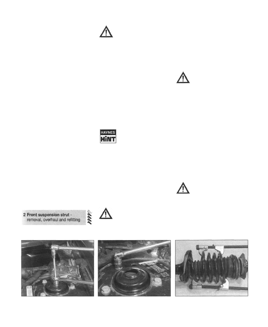
5 As the damper rod nut is difficult to slacken
with the strut on the bench, it is recommended
that it is slackened by half a turn whilst the
strut is still fitted to the vehicle. The damper
rod must be prevented from rotating as the nut
is slackened - this can be achieved by fitting a
13/16" spark plug socket with a hex head to
the damper rod nut, and inserting the hex
Allen bit through the top of the socket. The
socket can then be turned with a spanner,
whilst the damper rod is held stationary (see
illustration).
Warning: Slacken the nut by half
a turn only - do not remove the it
completely at this stage.
6 From the engine bay, detach the top of the
strut from the wing by removing the three
securing bolts; make a note their fitted
locations to ensure correct refitting, as there
are several possible mounting holes (see
illustration).
7 Lower the jack as necessary, to allow the
strut to clear the steering swivel member, but
avoid straining the suspension lower arm
mountings.
8 Remove the strut from the wheelarch.
Overhaul
Warning: Before attempting to
dismantle the front suspension
strut, the coil spring must be first
held in compression, using a
suitable tool. Adjustable coil spring
compressors are readily-available, and are
essential for this operation. DO NOT
attempt to dismantle the strut without
such a tool, as damage and/or personal
injury is likely.
Note: A new damper rod nut must be used on
reassembly.
9 Support the strut by clamping it in a vice;
avoid damaging the surface of the strut by
lining the vice jaws with aluminium or wooden
blocks. Avoid distorting the mounting bracket.
10 Using the spring compressor, contract the
coils of the spring just enough to relieve all
pressure from the upper spring seat (see
illustration).
11 Prise out the dust cap from the top of the
strut, to expose the retaining nut. Using the
method described in "Removal" to keep the
damper rod stationary, slacken the nut until it
can be removed by hand.
Warning: Ensure that the upper
spring seat has been completely
relieved of spring pressure before
removing the retaining nut.
12 Lift off the top bearing plate, upper spring
seat, coil spring (still compressed), lower
spring seat, compression stop and rubber
gaiter. Carefully release the spring
compression tool.
13 Examine the coil spring for signs of
general wear, deterioration or damage. In
particular, look for cracking and serious
2.5 Using a 13/16" spark plug socket and
hex Allen bit to slacken the strut damper
rod nut
2.6 Detach the top of the strut from the
wing by removing the three securing bolts
2.10 Using the spring compressor, contract
the coils of the spring just enough to relieve
all pressure from the upper spring seat
Нет комментариевНе стесняйтесь поделиться с нами вашим ценным мнением.
Текст