SAAB 9000. Manual — part 47
11 •4 Bodywork and fittings
is used in similar fashion to the bodywork filler
used on metal panels. The filler is usually
cured in twenty to thirty minutes, ready for
sanding and painting.
If the owner is renewing a complete
component himself, or if he has repaired it with
epoxy filler, he will be left with the problem of
finding a suitable paint for finishing which is
compatible with the type of plastic used. At
one time, the use of a universal paint was not
possible, owing to the complex range of
plastics encountered in body component
applications. Standard paints, generally
speaking, will not bond to plastic or rubber
satisfactorily. However, it is now possible to
obtain a plastic body parts finishing kit which
consists of a pre-primer treatment, a primer
and coloured top coat. Full instructions are
normally supplied with a kit, but basically, the
method of use is to first apply the pre-primer
to the component concerned, and allow it to
dry for up to 30 minutes. Then the primer is
applied, and left to dry for about an hour
before finally applying the special-coloured
top coat. The result is a correctly-coloured
component, where the paint will flex with the
plastic or rubber, a property that standard
paint does not normally posses.
Removal
1 Park the vehicle on a level surface, apply the
handbrake and chock the rear wheels. Raise
the front of the vehicle and rest it securely on
axle stands; refer to "Jacking, towing and
wheel changing" for guidance.
2 Where applicable, remove the retaining
screws, then lower the undertray and brake
cooling ducts away from the vehicle; note that
the front of the undertray is clipped onto the
trailing edge of the valance moulding.
3 Remove the retaining screws, and separate
the valance moulding from the bumper. Where
fitted, disconnect the wiring for the
driving/foglights and ambient air temperature
sensor.
4 Slacken the two through-bolts that secure
the bumper to the front subframe.
5 Disengage the ends of the bumper from the
body side mouldings, then pull the bumper
away from the front of the vehicle.
6 The bumper outer moulding can then be
separated from the inner metal core, by
removing the securing screws.
Refitting
7 Refit the bumper by reversing the removal
procedure; ensure that the lugs protruding
from the front wing engage with the
corresponding recesses in the ends of the
bumper.
Removal
1 Park the vehicle on a level surface, and
apply the handbrake.
2 Working directly behind the rear
wheelarches, remove the two screws that
secure the lower edges of the rear valance to
the side bumper mouldings.
3 Open the boot/tailgate, and lift the panel
above the spare wheel compartment, securing
it in the raised position. Prise the rubber
sealing strip away from the edge of the
loadspace, to expose the edge of the carpet
trim panel.
4 Pull the carpet away from the area behind
the rear light cluster, guiding the luggage
securing eyelet through the hole in the carpet.
5 The bumper assembly is secured by four
bolts; two on either side of the vehicle, directly
below the light clusters. The upper bolts also
act as mounting points for the luggage securing
eyelets. The lower bolts are concealed behind
plastic panels in the floor of the loadspace,
which can be prised out to expose the retaining
nuts. Remove all four nuts, supporting the
bumper as the last nut is removed.
6 Pull the bumper assembly squarely away
from the body, and recover the rubber
washers.
Refitting
7 Refit the bumper assembly by reversing the
removal procedure, tightening the mounting
nuts securely.
Warning: It is essential that the
help of an assistant is enlisted
during this operation.
Removal
1 Open the bonnet, and prop it up with a stout
pole.
2 Disconnect the washer jet hoses at the
three-way joint.
3 Lever out the pins from the hinges on both
sides of the bonnet; maintain a firm grip on the
bonnet as the pins are released, to prevent it
from tilting forwards.
4 Using a screwdriver, prise the clip from the
joint at the top of each bonnet support strut.
Separate the joint, and recover the washers.
Allow the struts to swivel forward and rest on
the wings.
5 With the help of your assistant, lift off the
bonnet and set it down on its edge, using a
dust sheet to protect the paintwork.
Refitting
6 Refit the bonnet by reversing the removal
process.
Front grille
7 Remove the four screws that secure the
grille to the front crossmember; these are
accessed through the front of the grille,
adjacent to the headlight units, and along the
top edge of the grille. Note when refitting that
the inside bottom edge of the grille has plastic
locating lugs at each end, which engage with
dowels, adjacent to the headlight units (see
illustration).
8.7 The inside bottom edge of the grille has
plastic locating lugs at each end (arrowed)
Removal
1 Refer to Section 8 and remove the front
grille.
2 Refer to Chapter 12 and remove the right-
hand indicator light unit.
3 Working underneath the bonnet locks,
release the stop nipples from the end of the
release cable inner at each lock.
4 Unscrew the cable clip from above the
right-hand headlight unit.
5 Remove the clips that secure the extension
cable to the underside of the front
crossmember.
6 Working inside the cabin, remove the
driver's door sill scuff plate, and the trim panel
Where serious damage has occurred, or
large areas need renewal due to neglect, it
means that complete new panels will need
welding-in, and this is best left to
professionals. If the damage is due to impact,
it will also be necessary to check completely
the alignment of the bodyshell, and this can
only be carried out accurately by a Saab
dealer, using special jigs. If the body is left
misaligned, it is primarily dangerous, as the
car will not handle properly, and secondly,
uneven stresses will be imposed on the
steering, suspension and possibly
transmission, causing abnormal wear, or
complete failure, particularly to such items as
the tyres.
Bonnet
Bodywork and fittings 11 •5
surrounding the bonnet release handle.
Extract the fixings, and lower the sound
insulation panel away from the underside of
the steering column/facia.
7 Prise off the clip, and release the cable
outer from the stop. Pull the cable towards the
handle, and free the cable inner nipple from it.
8 Pull the entire cable through into the cabin
area. If it proves difficult to remove, greater
access to the cable run may be gained by
jacking up the vehicle, removing the right-
hand front roadwheel - refer to "Jacking,
towing and wheel changing" - and removing
the inner wing liner - refer to Section 22.
Refitting
9 Refit the cable by reversing the removal
process. Adjust both cable stops at the bonnet
locks, to ensure that the locks release correctly
when the handle is operated. Check also that
when the handle is at rest, the bonnet is held
securely in closed position by the locks on
both sides; pull up firmly at each corner of the
bonnet to assess this. If necessary, adjust the
striker pin lengths as described in Section 10.
Removal
1 Open the bonnet, then remove the four
screws that secure the front grille in position.
2 Referring to the relevant paragraphs of
Section 9, free the release cable from the
bonnet lock actuator levers.
3 Remove the two securing bolts at either
side of the lock unit, and withdraw it from the
crossmember.
Refitting
4 Refit the locks by reversing the removal
procedure; when refitting the release cable,
adjust both cable stops at the bonnet locks, to
ensure that the locks release correctly when
the handle is operated. Check also that when
the handle is at rest, the bonnet is held
securely in closed position by the locks on
both sides; pull up firmly at each corner of the
bonnet to assess this. If necessary, adjust the
striker pin lengths as described below.
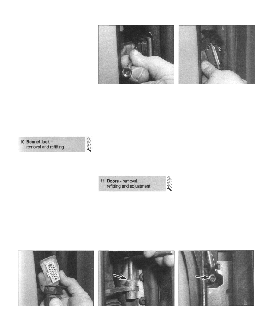
11.2a Using a small screwdriver, prise out
the locking bar from the connector...
Striker pin adjustment
5 If the striker pin is badly adjusted such that
it is too long, the bonnet will be loose in the
closed position and may rattle; more
importantly, there is the risk that the lock may
burst open. Similarly, if the striker pin is too
short, closing the bonnet may require
excessive force, and the risk of damage or
only partial engagement of the locks is
potential hazard.
6 To adjust the length of the striker pin,
slacken the locknut and turn the pin (clockwise
to retract, anti-clockwise to extend) using a
screwdriver inserted into the slotted end.
When the desired length is achieved, re-
tighten the locknut and re-check the security
of the bonnet locks.
11.2b . . . this will allow the locking
mechanism to compress, releasing it from
the aperture in the body
two halves (see illustration). Note: On earlier
models, it will be necessary to remove the
door inner trim panel (refer to Section 12) and
pull the harness through the grommet in the
edge of the door, after unplugging the
electrical connectors individually.
4 Remove the screw and detach the restrainer
bar from the anchoring point on the body (see
illustration). Note: On earlier models, it will be
necessary to tap out the roll pin from the
restrainer bar, using a hammer and punch; a
new roll pin must then be used on refitting.
5 On later models, remove the grub screws
from the upper and lower hinges (see
illustration).
6 Open the door wide, so that the notch and
lug on the two sides of the hinge line up.
7 Lift the door squarely off its hinges, and set
it down on a dust sheet to protect the edges.
Refitting
8 Refit the door by reversing the removal
procedure.
Rear doors
Removal
9 Refer to Section 12, and remove the inner
trim panel.
10 Unplug all the wiring harness connectors
to the central locking servo, electric window
motor and "door open" sensor (where fitted),
labelling them to aid refitting later. Withdraw
the harness through the grommet in the edge
of the door.
11.3 Withdraw the connector from the
aperture, together with the rubber seal,
and unplug the two halves
11.4 Remove the screw (arrowed) and
detach the restrainer bar from the
anchoring point on the body
11.5 On later models, remove the grub
screws from the upper and lower hinges
Front doors
Removal
1 Disconnect the battery negative cable, and
position it away from the terminal.
2 Open the door to gain access to the wiring
harness connector. Using a small screwdriver,
prise out the locking bar from the connector
housing; this will allow the locking mechanism
to compress, releasing it from the aperture in
the body (see illustrations).
3 Withdraw the connector from the aperture,
together with the rubber seal, and unplug the
11 •6 Bodywork and fittings
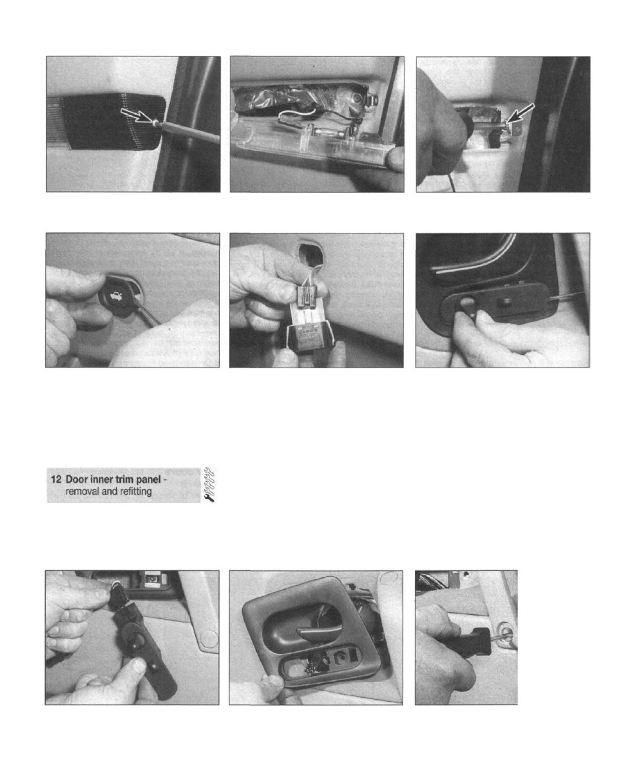
12.2a Remove the screw (arrowed) from
the bi-colour courtesy lamp at the edge of
the door
12.2b Lift off the lens, disengaging the
leading edge from the rear of the door
stowage bin
12.3 Remove the retaining screw (arrowed)
from the courtesy light housing
12.4a Prise out the boot/tailgate release
switch, using a flat-bladed screwdriver . . .
11 Follow the procedure described for the
removal of the front door.
Refitting
12 Refit the door by reversing the removal
procedure.
Front door
Removal
1 Disconnect the battery negative cable, and
position it away from the terminal.
12.4b . . . then unplug the connector
2 Remove the screw from the bi-colour
courtesy light at the edge of the door. Lift off
the lens, disengaging the leading edge from
the rear of the door stowage bin (see
illustrations).
3 Remove the retaining screw from the
courtesy light housing (see illustration).
4 If the driver's door panel is being removed,
prise out the boot/tailgate release switch,
using a flat-bladed screwdriver. Unplug the
connector, and label the cables on the harness
side, to aid refitting later (see illustrations).
5 Prise out the plastic switch panel directly
beneath the interior door handle. On the
driver's door, the panel houses the electric
mirror switches; on both rear doors, it houses
12.5a Prise out the plastic switch panel
directly beneath the interior door handle...
the electric window switches; (a blank panel is
fitted to the front passenger door). Where
applicable, unplug the connectors, and label
the cables on the harness side, to aid refitting
later (see illustrations).
6 Remove the screw beneath the switch
panel, and lift out the door handle bezel (see
illustration).
7 Prise the plastic caps from the top and
bottom of the door grab handle, then remove
the retaining screws and lift off the handle (see
illustration). Note that on later models, the
grab handle remains attached to the door
panel, but the mounting screws still need to be
removed.
8 Remove the plastic caps from both ends of
12.5b ... then unplug the connectors
(where applicable), labelling the cables on
the harness side, to aid refitting later
12.6 Remove the screw beneath the switch
panel, and lift out the door handle bezel
12.7 Remove the door grab handle
retaining screws
'
Bodywork and fittings 11 •7
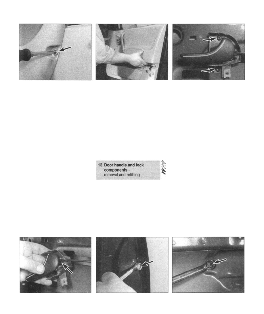
12.8 Slacken and remove the screws at
either end of the door stowage bin
the door stowage bin, then slacken and
remove the screws (see illustration). Note
that these screws actually secure the door trim
panel to the door; the stowage bin itself
remains attached to the door panel.
9 Use a wide-bladed flat instrument, such as
a spatula or a filling knife padded with PVC
tape, to release the press-stud fixings from the
outer rim of the panel. Insert the instrument to
one side of each fixing, between the trim panel
and the door, and carefully lever out the panel
until the press-stud disengages. (When the
panel is refitted, these studs can simply be
ined up with their mounting holes, and
pressed back into position.)
10 Lift the panel away from the door, prising
the trim strip out of the window aperture, and
guiding the lock release button through the
hole in the top of the panel (see illustration).
11 On earlier models, there will be a plastic
moisture-resistant film stretched over the door
panel. Start at one corner, and carefully peel
the film away from the door, keeping it taut to
stop it sticking to itself and anything else,
Ideally, the film should be renewed once
disturbed. However, if the old one is to be re-
used, find a suitable place to hang the film
upright by its top edge, until it is refitted.
12 On later models, the door is lined with a
combination of expanded foam sheeting, and
wads of sound insulation material. Both are
held in place with steel spring clips, which
be removed with care to avoid
12.10 Lift the panel away from the door
scratching the paintwork and inducing
corrosion.
Refitting
13 Refit the panel by reversing the removal
procedure.
Rear door
14 The procedure for removing the rear door
trim panel is essentially the same as that for
the front doors, with the exception that later
models have a window demister fan screwed
to the inside of the panel; remember to unplug
its cabling at the connector, as the trim panel
is removed.
13.4 Remove the two handle assembly
retaining screws
illustration), then lift the handle assembly
away from the door.
5 Release the link rod from the plastic clip at
the rear of the interior handle assembly. If
necessary, release the link rod from the
intermediate guide clip first (see illustration).
Refitting
6 Refit the handle assembly by reversing the
removal procedure.
Exterior door handles
Note: This procedure is applicable to both the
front and rear exterior door handles, with the
exception that references to the lock cylinder
should be ignored when working on the rear
doors.
Removal
7 Ensure that the window glass is fully raised.
Disconnect the battery negative cable, and
position it away from the terminal.
8 Refer to Section 12 and remove the door
interior trim panel.
9 Remove the two handle retaining screws;
one at the rear edge of the door, adjacent to
the outer lock mechanism, and one directly
behind the handle assembly, accessible
through the void in the door (see
illustrations).
10 Remove the window glass guide channel,
after removing the retaining screws from the
rear edge of the door. Unclip the central
13.5 Release the link rod from the plastic
clip at the rear of the interior handle
assembly
13.9a Remove the two handle retaining
screws; one at the rear edge of the door,
adjacent to the outer lock mechanism ...
13.9b ... and one directly behind the
handle assembly, accessible through the
void in the door
must
Interior door handles
Note: This procedure is applicable to both the
front and rear interior door handles.
Removal
1 Ensure that the window glass is fully raised.
2 Disconnect the battery negative cable, and
position it away from the terminal.
3 Refer to Section 12 and remove the door
interior trim panel.
4 Remove the two retaining screws (see
Нет комментариевНе стесняйтесь поделиться с нами вашим ценным мнением.
Текст