SAAB 9000. Manual — part 17
2B•14 Engine removal and general overhaul procedures
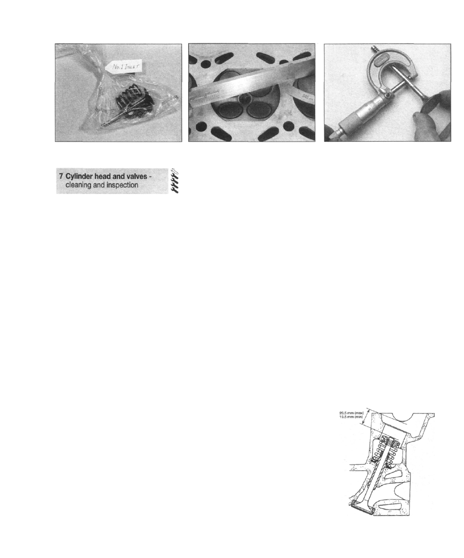
6.7b Place each valve and its associated
components in a labelled polythene bag
1 Thorough cleaning of the cylinder head and
valve components, followed by a detailed
inspection, will enable you to decide how
much valve service work must be carried out
during the engine overhaul. Note: If the engine
has been severely overheated, it is best to
assume that the cylinder head is warped -
check carefully for signs of this.
Cleaning
2 Scrape away all traces of old gasket
material from the cylinder head.
3 Scrape away the carbon from the
combustion chambers and ports, then wash
the cylinder head thoroughly with paraffin or a
suitable solvent.
4 Scrape off any heavy carbon deposits that
may have formed on the valves, then use a
power-operated wire brush to remove
deposits from the valve heads and stems.
Inspection
Note: Be sure to perform all the following
inspection procedures before concluding that
the services of a machine shop or engine
overhaul specialist are required. Make a list of
all items that require attention.
Cylinder head
5 Inspect the head very carefully for cracks,
evidence of coolant leakage, and other
damage. If cracks are found, a new cylinder
head should be obtained.
6 Use a straight-edge and feeler blade to
check that the cylinder head surface is not
distorted (see illustration). If it is, it may be
possible to have it machined, provided that
the cylinder head is not reduced to less than
the specified height.
7 Examine the valve seats in each of the
combustion chambers. If they are severely
pitted, cracked, or burned, they will need to be
renewed or re-cut by an engine overhaul
specialist. If they are only slightly pitted, this
can be removed by grinding-in the valve
heads and seats with fine valve-grinding
compound, as described below. Note that the
7.6 Checking the cylinder head gasket face
for distortion
exhaust valves have a hardened coating and,
although they may be ground-in with paste,
they must not be machined.
8 Check the valve guides for wear by inserting
the relevant valve, and checking for side-to-
side motion of the valve. A very small amount
of movement is acceptable. If the movement
seems excessive, remove the valve. Measure
the valve stem diameter (see below), and
renew the valve if it is worn. If the valve stem is
not worn, the wear must be in the valve guide,
and the guide must be renewed. The renewal
of valve guides is best carried out by a Saab
dealer or engine overhaul specialist, who will
have the necessary tools available.
Valves
9 Examine the head of each valve for pitting,
burning, cracks, and general wear. Check the
valve stem for scoring and wear ridges. Rotate
the valve, and check for any obvious
indication that it is bent. Look for pits and
excessive wear on the tip of each valve stem.
Renew any valve that shows any such signs of
wear or damage.
10 If the valve appears satisfactory at this
stage, measure the valve stem diameter at
several points using a micrometer (see
illustration). Any significant difference in the
readings obtained indicates wear of the valve
stem. Should any of these conditions be
apparent, the valve(s) must be renewed.
11 If the valves are in satisfactory condition,
they should be ground (lapped) into their
respective seats, to ensure a smooth, gas-
tight seal. If the seat is only lightly pitted, or if it
has been re-cut, fine grinding compound
should be used to produce the required finish.
Coarse valve-grinding compound should not
be used, unless a seat is badly burned or
deeply pitted. If this is the case, the cylinder
head and valves should be inspected by an
expert, to decide whether seat re-cutting, or
even the renewal of the valve or seat insert
(where possible) is required.
12 Valve grinding is carried out as follows.
Place the cylinder head upside-down on a
bench.
13 Smear a trace of (the appropriate grade of)
valve-grinding compound on the seat face,
and press a suction grinding tool onto the
7.10 Measuring a valve stem diameter
valve head. With a semi-rotary action, grind
the valve head to its seat, lifting the valve
occasionally to redistribute the grinding
compound. A light spring placed under the
valve head will greatly ease this operation.
14 If coarse grinding compound is being
used, work only until a dull, matt even surface
is produced on both the valve seat and the
valve, then wipe off the used compound, and
repeat the process with fine compound. When
a smooth unbroken ring of light grey matt
finish is produced on both the valve and seat,
the grinding operation is complete. Do not
grind-in the valves any further than absolutely
necessary, or the seat will be prematurely
sunk into the cylinder head.
15 When all the valves have been ground-in,
carefully wash off alI traces of grinding
compound using paraffin or a suitable solvent,
before reassembling the cylinder head.
16 To ensure that the hydraulic cam followers
operate correctly, the depth of the valve stems
below the camshaft bearing surface must be
within certain limits. It may be possible to
obtain a Saab checking tool from a dealer, but
if not, the check may be made using a steel
rule and straight-edge. Check that the
dimension is within the limits given in the
Specifications by inserting each valve it its
guide in turn, and measuring the dimension
between the end of the valve stem and the
camshaft bearing surface (see illustration).
H 28527
7.16 Check the depth of the valve stems
below the camshaft bearing surface
Engine removal and general overhaul procedures 2B•15
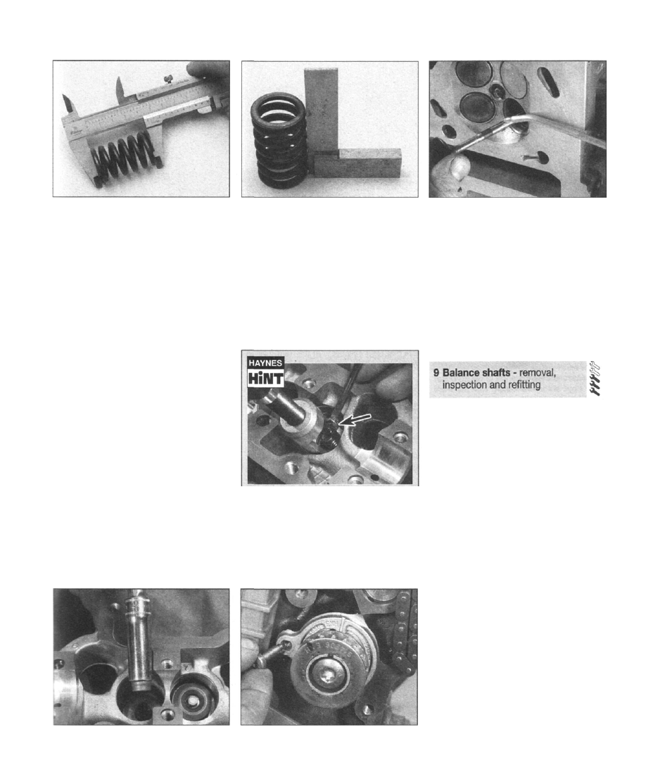
7.18 Checking the valve spring free length
17 If the dimension is not within the specified
limits, adjustment must be made either to the
end of the valve stem or to the valve seat
height. If lower than the minimum amount, the
length of the valve stem must be reduced, and
if more than the maximum amount, the valve
seat must be milled. Seek the advice of a Saab
dealer or engine reconditioning specialist.
Valve components
18 Examine the valve springs for signs of
damage and discoloration, and measure their
free length (see illustration).
19 Stand each spring on a flat surface, and
check it for squareness (see illustration). If
any of the springs are less than the minimum
free length, or are damaged, distorted or have
ost their tension, obtain a complete new set of
springs.
20 Obtain new valve stem oil seals,
regardless of their apparent condition.
8 Cylinder head - reassembly
1 Lubricate the stems of the valves, and insert
the valves into their original locations (see
illustration). If new valves are being fitted,
insert them into the locations to which they
have been ground.
2 Working on the first valve, dip the new valve
stem seal in fresh engine oil. Carefully locate it
over the valve and onto the guide. Take care
not to damage the seal as it is passed over the
7.19 Checking the valve springs for
squareness
valve stem. Use a suitable socket or metal
tube to press the seal firmly onto the guide
(see illustration).
3 Refit the valve spring followed by the spring
retainer, then locate the plastic protector in the
hydraulic cam follower bore.
4 Compress the valve spring, and locate the
split collets in the recess in the valve stem.
Release the compressor and remove the
protector, then repeat the procedure on the
remaining valves.
Use a little dab of grease to locate the
collets on the valve stems, and to hold
them in place while the spring
compressor is released
5 With all the valves installed, place the
cylinder head flat on the bench and, using a
hammer and interposed block of wood, tap
8.2 Using a socket to fit the valve stem
seals
9.7a Unscrew the bearing retaining
bolts..
8.1 Inserting a valve in the cylinder head
the end of each valve stem to settle the
components.
6 Refit the hydraulic cam followers and
camshafts with reference to Part A, Section 8.
7 Refit the external components removed in
Section 6. When refitting the distributor
blanking plug, check and if necessary renew
the O-ring seal.
8 The cylinder head may now be refitted as
described in Part A of this Chapter.
Removal
1 Position the crankshaft at TDC compression
for No 1 piston (timing chain end of the engine)
as described in Chapter 2A, Section 3.
2 Remove the timing cover as described in
Chapter 2A, Section 5.
3 The balance shafts are "timed" at TDC, but
since they rotate at twice the speed of the
crankshaft, they may also be correctly "timed"
at BDC. Check that the timing marks on the
shafts are correctly aligned with the marks on
the bearing brackets. As an extra precaution,
apply dabs of paint to the chain and
sprockets, to ensure correct refitting. Note
that the balance shaft sprockets are marked
"inlet" and "exhaust" for position, but the front
bearings are marked identically. However, as
the bearings are located with single bolts, the
"inlet" and "exhaust" marks will always be
correctly located at the top of the bearings.
4 Unbolt the balance shaft chain upper guide,
then remove the tensioner and side guide.
5 Unscrew the retaining bolt and remove the
idler from the block.
6 Release the chain from the balance shaft
sprockets and crankshaft sprocket.
7 Unscrew the bearing retaining bolts, and
withdraw the balance shafts from the cylinder
block (see illustrations). Keep the shafts
identified for position.
8 Unscrew the retaining bolts, and remove the
sprockets from the ends of the balance shafts,
while holding each shaft in a soft-jawed vice.
2B•16 Engine removal and general overhaul procedures
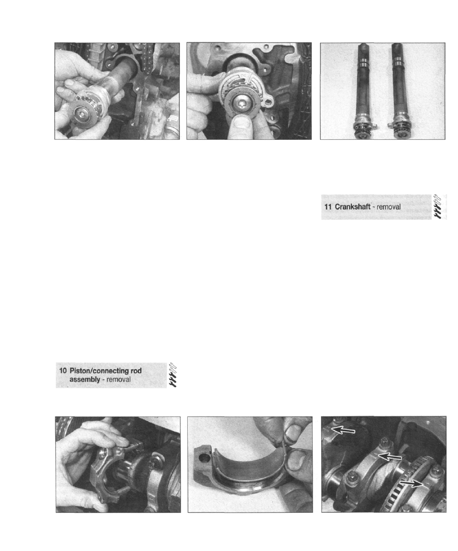
9.7b . . . and withdraw the exhaust balance
shaft from the cylinder block
Inspection
9 Clean the balance shafts and examine the
bearing journals for wear and damage. The
bearings inside the cylinder block should also
be examined. If these are excessively worn or
damaged, get advice from a Saab dealer or
engine reconditioner.
Refitting
10 Fit the sprockets to the ends of the
balance shafts, and tighten the retaining bolts.
11 Lubricate the bearing journals with clean
engine oil, then insert the balance shafts in the
cylinder block in their correct positions.
12 Locate the balance shaft chain sprocket
on the front of the crankshaft, with the word
"Saab" facing outwards.
13 Fit the chain to the sprockets, and refit the
idler to the front of the block, making sure that
the timing marks remain aligned correctly.
14 Refit the side guide, tensioner and upper
guide to the balance shaft chain.
15 Rotate the crankshaft one turn, and check
that the balance shaft sprockets are still
correctly aligned.
16 Refit the timing cover with reference to
Chapter 2A, Section 5.
1 Remove the cylinder head, sump and oil
pump pick-up/strainer as described in Part A
of this Chapter.
9.7c Removing the inlet balance shaft from
the cylinder block
2 If there is a pronounced wear ridge at the
top of any bore, it may be necessary to
remove it with a scraper or ridge reamer, to
avoid piston damage during removal. Such a
ridge indicates excessive wear of the cylinder
bore.
3 Using a hammer and centre-punch, paint or
similar, mark each connecting rod big-end
bearing cap with its respective cylinder number
on the flat machined surface provided; if the
engine has been dismantled before, note
carefully any identifying marks made previously.
Note that No 1 cylinder is at the transmission
(flywheel/driveplate) end of the engine.
4 Turn the crankshaft to bring pistons 1 and 4
to BDC (bottom dead centre).
5 Unscrew the nuts from No 1 piston big-end
bearing cap. Take off the cap, and recover the
bottom half bearing shell. If the bearing shells
are to be re-used, tape the cap and the shell
together (see illustrations).
6 To prevent the possibility of damage to the
crankshaft bearing journals, tape over the
connecting rod stud threads.
7 Using a hammer handle, push the piston up
through the bore, and remove it from the top
of the cylinder block. Recover the bearing
shell, and tape it to the connecting rod for
safe-keeping.
8 Loosely refit the big-end cap to the
connecting rod, and secure with the nuts - this
will help to keep the components in their
correct order.
9 Remove No 4 piston assembly in the same
way.
9.7d The two balance shafts removed from
the engine
10 Turn the crankshaft through 180° to bring
pistons 2 and 3 to BDC (bottom dead centre),
and remove them in the same way.
1 Remove the timing chain and sprocket, the
sump and oil pump pick-up/strainer/transfer
tube, and the flywheel/driveplate, as described
in Part A of this Chapter.
2 Remove the pistons and connecting rods,
as described in Section 10. Note: If no work is
to be done on the pistons and connecting
rods, there is no need to remove the cylinder
head, or to push the pistons out of the cylinder
bores. The pistons should just be pushed far
enough up the bores that they are positioned
clear of the crankshaft journals.
3 Check the crankshaft endfloat with
reference to Section 14, then proceed as
follows.
4 Unbolt and remove the crankshaft rear oil
seal housing from the end of the cylinder
block, noting the correct fitted locations of the
locating dowels. If the locating dowels are a
loose fit, remove them and store them with the
housing for safe-keeping. Remove the gasket.
5 Identification numbers should already be
cast onto the base of each main bearing cap
(see illustration). If not, number the cap and
crankcase using a centre-punch, as was done
for the connecting rods and caps.
10.5a Removing a big-end bearing cap
10.5b Removing a bearing shell from a big-
end bearing cap
11.5 The main bearing caps are numbered
from the timing chain end of the engine
Engine removal and general overhaul procedures 2B•17
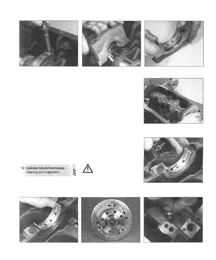
11.6a Unscrew and remove the main
bearing cap bolts...
6 Unscrew and remove the main bearing cap
retaining bolts, and withdraw the caps,
complete with bearing shells (see
illustrations). Tap the caps with a wooden or
copper mallet if they are stuck.
7 Remove the bearing shells from the caps,
but keep them with their relevant caps and
identified for position to ensure correct
refitting (see illustration).
8 Carefully lift the crankshaft from the
crankcase (see illustration).
9 Remove the upper bearing shells from the
crankcase, keeping them identified for
position. Also remove the thrustwashers at
each side of the centre main bearing, and
store them with the bearing cap (see
illustrations).
10 With the crankshaft removed on B2O4 and
B234 engines, the crankshaft position sensor
reluctor may be removed if necessary, by
unscrewing the screws and withdrawing the
reluctor over the end of the crankshaft (see
illustration). Note that the screws are
arranged so that it is only possible to refit the
reluctor in one position.
Cleaning
1 Remove all external components and
electrical switches/sensors from the block. For
complete cleaning, the core plugs should
11.6b . . . and remove the main bearing
caps
ideally be removed, as follows. Drill a small
hole in the plugs, then insert a self-tapping
screw into the hole. Pull out the plugs by
pulling on the screw with a pair of grips, or by
using a slide hammer. Also unbolt the four oil
jets from the crankcase on B2O4/B234
engines (see illustration).
2 Scrape all traces of sealant from the
cylinder block/crankcase, taking care not to
damage the gasket/sealing surfaces.
3 Remove all oil gallery plugs (where fitted).
The plugs are usually very tight - they may
have to be drilled out, and the holes re-
tapped. Use new plugs when the engine is
reassembled.
4 If the cylinder block/crankcase is extremely
dirty, it should be steam-cleaned.
5 Clean all oil holes and oil galleries, and flush
all internal passages with warm water until the
water runs clear. Dry thoroughly, and apply a
light film of oil to all mating surfaces, to
prevent rusting. Also oil the cylinder bores. If
you have access to compressed air, use it to
speed up the drying process, and to blow out
all the oil holes and galleries.
Warning: Wear eye protection
when using compressed air!
6 If the cylinder block is not very dirty, you
can do an adequate cleaning job with hot (as
hot as you can stand!), soapy water and a stiff
brush. Take plenty of time, and do a thorough
job. Regardless of the cleaning method used,
11.7 Removing a main bearing shell from
its cap
2B
11.8 Lifting the crankshaft from the
crankcase
11.9a Removing the thrustwashers
(arrowed)...
11.9b . . . and main bearing shells
11.10 Location of the screws securing the
crankshaft position sensor reluctor
12.1 Removing an oil jet from the
crankcase
Нет комментариевНе стесняйтесь поделиться с нами вашим ценным мнением.
Текст