SAAB 9000. Manual — part 8
1•18
Every 48 000 miles or 3 years
5 Loosen the drain plug in the radiator bottom
tank, and allow the coolant to drain into the
container.
6 When the flow of coolant stops, reposition
the container below the cylinder block drain
plug. On balance shaft engines, there are two
cylinder block drain plugs, one located on the
front left-hand side, and the other located on
the rear left-hand side. With the plug(s)
removed, allow the coolant to drain from the
cylinder block.
7 Refit and tighten the radiator and cylinder
block drain plugs.
8 If the coolant has been drained for a reason
other than renewal, then provided it is clean
and less than three years old, it can be re-
used.
Cooling system flushing
9 If coolant renewal has been neglected, or if
the antifreeze mixture has become diluted,
then in time, the cooling system may gradually
lose efficiency, as the coolant passages
become restricted due to rust, scale deposits,
and other sediment. The cooling system
efficiency can be restored by flushing the
system clean.
10 The radiator should be flushed
independently of the engine, to avoid
unnecessary contamination.
Radiator flushing
11 To flush the radiator, first disconnect the
top and bottom hoses from the radiator.
12 Insert a garden hose into the radiator top
inlet. Direct a flow of clean water through the
radiator, and continue flushing until clean
water emerges from the radiator bottom
outlet.
13 If after a reasonable period, the water still
does not run clear, the radiator can be flushed
with a good proprietary cleaning agent. It is
important that their manufacturer's
instructions are followed carefully. If the
contamination is particularly bad, remove the
radiator then insert the hose in the radiator
bottom outlet, and reverse-flush the radiator.
Engine flushing
15 To flush the engine, first remove the
thermostat as described in Chapter 3, then
temporarily refit the thermostat cover.
16 With the top and bottom hoses
disconnected from the radiator, insert a
garden hose into the radiator top hose. Direct
a clean flow of water through the engine, and
continue flushing until clean water emerges
from the radiator bottom hose.
17 On completion of flushing, refit the
thermostat and reconnect the hoses with
reference to Chapter 3.
18 Check that the radiator and cylinder block
drain plugs are in place and tight.
19 Remove the container from under the car,
then refit the centre panel beneath the
radiator, and lower the car to the ground.
Cooling system filling
20 Before attempting to fill the cooling
system, make sure that all hoses and clips are
in good condition, and that the clips are tight.
Note that an antifreeze mixture must be used
all year round, to prevent corrosion of the
engine components (see following sub-
Section).
21 Pour the correct amount of antifreeze (see
"Lubricants, fluids and capacities") into a
container, then add water until the total
amount is approximately 6.5 litres.
22 Slowly fill the system through the
expansion tank filler neck, allowing time for
trapped air to escape through the purge line.
Every 96 000 miles
Warning: Before carrying out the
following operation, refer to the
precautions given in "Safety
first!" at the beginning of this
manual, and follow them implicitly. Petrol
is a highly-dangerous and volatile liquid,
and the precautions necessary when
handling it cannot be overstressed.
1 On some early models with the LH-Jetronic
fuel injection system, the fuel filter is located in
the engine compartment between the battery
and the false bulkhead. On later models with
both the LH-Jetronic and Trionic fuel Injection
systems, the filter is adjacent to the fuel tank
underneath the rear of the car.
2 Depressurise the fuel system with reference
to Chapter 4A, Section 9.
Early models with LH-Jetronic fuel
injection system
3 Clean the areas around the fuel filter inlet
and outlet unions.
4 Position a small container or cloth rags
beneath the filter, to catch spilt fuel.
5 Unscrew the banjo coupling bolt on the
bottom of the filter, while holding the coupling
with a further spanner. Recover the sealing
washers.
6 Unscrew the banjo coupling bolt on the top
of the filter, using the same procedure.
7 Noting the direction of the arrow marked on
the filter body, loosen the retaining clip and
withdraw the filter from the engine
compartment.
8 Locate the new filter in the retaining clip,
and tighten the clip. Make sure that the flow
arrow on the filter body is pointing towards the
outlet which leads to the fuel injection rail.
9 Check the condition of the sealing washers,
and renew them if necessary.
10 Refit the banjo couplings and hoses to the
Top-up to the "MAX" mark on the side of the
expansion tank.
23 Refit and tighten the filler cap.
24 Start the engine, and run it at a fast idle
speed until the cooling fan cuts in, and then
cuts out. This will purge any remaining air from
the system. Stop the engine.
25 Allow the engine to cool, then check the
coolant level with reference to Section 3 of this
Chapter. Top-up the level if necessary. Saab
recommend that the level be checked again
after a few days, and topped-up as necessary.
Antifreeze mixture
26 The antifreeze should always be renewed
at the specified intervals. This is necessary not
only to maintain the antifreeze properties, but
also to prevent corrosion which would
otherwise occur as the corrosion inhibitors
become progressively less effective.
27 Always use an ethylene-glycol based
antifreeze which is suitable for use in mixed-
metal cooling systems. The percentage of
antifreeze and levels of protection are
indicated in the Specifications.
28 Before adding antifreeze, the cooling
system should be completely drained,
preferably flushed, and all hoses checked for
condition and security.
29 After filling with antifreeze, a label should
be attached to the expansion tank filler neck,
stating the type and concentration of
antifreeze used, and the date installed. Any
subsequent topping-up should be made with
the same type and concentration of antifreeze.
30 Do not use engine antifreeze in the
windscreen/tailgate washer system, as it will
cause damage to the vehicle paintwork. A
screenwash additive should be added to the
washer system, in the quantities stated on the
bottle.
top and bottom of the filter, together with the
sealing washers. Tighten the bolts securely,
while holding the couplings with a further
spanner.
11 Wipe away any excess fuel.
Later models with LH-Jetronic or
Trionic systems
12 Chock the front wheels, then jack up the
rear of the car and support on axle stands (see
"Jacking, towing and wheel changing").
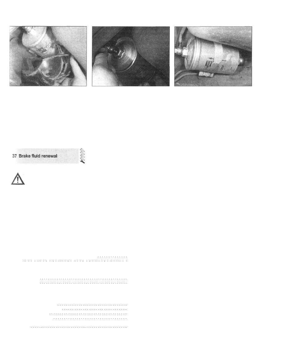
13 Pull off the plastic guard where fitted (see
illustration), then clean the areas around the
fuel filter inlet and outlet unions.
14 Position a small container or cloth rags
beneath the filter to catch spilt fuel.
15 Unscrew the banjo coupling bolts from
each end of the filter (see illustration), while
holding the coupling with a further spanner.
Recover the sealing washers.
16 Noting the direction of the arrow marked
on the filter body, loosen the retaining clip and
withdraw the filter from under the car.
Every 96 000 miles
36.13 Removing the plastic guard from the
bottom of the fuel filter
17 Locate the new filter in the retaining clip,
and tighten the clip. Make sure that the flow
arrow on the filter body is pointing towards the
outlet which leads to the engine compartment
(see illustration).
18 Check the condition of the sealing
washers, and renew them if necessary.
36.15 Unscrewing the banjo bolts from the
ends of the filter
36.17 Note the direction of the arrow on the
filter body
19 Refit the banjo couplings and hoses to All models
each end of the filter, together with the sealing
washers. Tighten the bolts securely, while
holding the couplings with a further spanner.
20 Wipe away any excess fuel, refit the
plastic cover where fitted, then lower the car
to the ground.
1 The procedure is similar to that for the
bleeding of the hydraulic system as described
in Chapter 9, except that the brake fluid
reservoir should be emptied by syphoning,
using a clean poultry baster or similar before
starting, and allowance should be made for
the old fluid to be expelled when bleeding a
section of the circuit. To prevent
contamination from the fluid in the clutch
hydraulic system (which uses the same
reservoir) the latter system should be bled as
described in Chapter 6 after bleeding the
brake system.
2 Working as described in Chapter 9, open
the first bleed screw in the sequence, and
pump the brake pedal gently until nearly all the
old fluid has been emptied from the fluid
reservoir. Top-up to the "MAX" level with new
fluid, and continue pumping until only the new
fluid remains in the reservoir, and new fluid
can be seen emerging from the bleed screw.
21 Start the engine, and check the filter hose
connections for leaks.
22 The old filter should be disposed of safely,
bearing in mind that it will be highly
inflammable.
Tighten the screw, and top the reservoir level
up to the "MAX" level line.
3 Old hydraulic fluid is invariably much darker
in colour than the new, making it easy to
distinguish the two.
4 Work through all the remaining bleed
screws in the sequence, until new fluid can be
seen at all of them. Be careful to keep the
master cylinder reservoir topped-up to above
the "MIN" level at all times, or air may enter the
system and greatly increase the length of the
task.
5 When the operation is complete, check that
all bleed screws are securely tightened, and
that their dust caps are refitted. Wash off all
traces of spilt fluid, and recheck the reservoir
fluid level.
6 Check the operation of the brakes before
taking the car on the road.
Cooling system
Antifreeze mixture:
28% antifreeze
50% antifreeze
Note: Refer to antifreeze manufacturer for latest recommendations.
Fuel system
Air filter element:
Non-Turbo models to 1988
Non-Turbo models from 1989
Turbo models to 1987
Turbo models from 1988
Fuel filter:
All models
1.0 litre
Champion C104
Protection down to -15 C (5 F)
Protection down to -30 C (-22 F)
Champion U545
Champion V423
Champion U545
Champion V423
Champion L204
Every 2 years
Warning: Brake hydraulic fluid
can harm your eyes and damage
painted surfaces, so use extreme
caution when handling and
pouring it. Do not use fluid that has been
standing open for some time, as it absorbs
moisture from the air. Excess moisture
content can cause a dangerous loss of
braking effectiveness.
Specifications
Difference between MIN and MAX marks on dipstick
Oil filter
1•19

1•20
Specifications
Ignition system
Spark plugs:
1985 cc (non-Turbo with Hall-effect ignition) Champion RC9YCC
1985 cc (non-Turbo with Direct Ignition) Champion RC9YCC4
1985 cc (Turbo with Hall-effect ignition) Champion RC7YCC
1985 cc (Turbo with Direct Ignition) Champion RC7YCC4
2290 cc (all models with Direct Ignition) Champion RC7YCC4
Spark plug electrode gap*:
RC9YCC, RC7YCC 0.8 mm
RC9YCC4, RC7YCC4 1.0 mm
Ignition HT lead set:
Non-Turbo models Champion LS-04
Turbo models Champion LS-12
Ignition HT lead resistance Approximately 600 ohms per 100 mm length
*The spark plug gap quoted is that recommended by Champion for their specified plugs listed above. If spark plugs of any other type are to be
fitted, refer to their manufacturer's recommendations.
Brakes
Brake pad friction material minimum thickness 4.0 mm
Tyres
Tyre size 195/65 R15T, 195/65 VR15, 205/60 ZR15, 205/50 ZR16, or 205/55
ZR16
Pressures (tyres cold) - psi (bars): Front Rear
1 to 3 persons:
195/65 R15T 30 (2.1) 30 (2.1)
195/65 VR15 30 (2.1) 30 (2.1)
205/60 ZR15 32 (2.2) 32 (2.2)
205/50 ZR16 35 (2.4) 35 (2.4)
205/55 ZR16 35 (2.4) 35 (2.4)
Maximum load (up to 99 mph) - where different to above:
205/50 ZR16 38 (2.6) 38 (2.6)
Maximum load (over 99 mph):
195/65 R15T 33 (2.3) 33 (2.3)
195/65 VR15 38 (2.6) 38 (2.6)
205/60 ZR15 39 (2.7) 39 (2.7)
205/50 ZR16 : 43 (3.0) 43 (3.0)
205/55 ZR16 41 (2.8) 41 (2.8)
Spare wheel (maximum 50 mph):
115/70 R16 60 (4.2) 60 (4.2)
175/70 R15T 36 (2.5) 36 (2.5)
Note: The pressures quoted are for 1992-on models. Consult manufacturers handbook for other models.
Note: Pressures apply only to original-equipment tyres, and may vary if any other make or type is fitted; check with the tyre manufacturer or supplier
for correct pressures if necessary.
Manual transmission filler, level and drain plugs
Roadwheel bolts
Spark plugs
Wiper blades
Windscreen and tailgate
Torque wrench settings
Automatic transmission drain plug
Engine oil drain plug
Ignition cartridge (models with Direct Ignition)
2A•1
Chapter 2 Part A:
Engine in-car repair procedures
Contents
Camshaft(s) and hydraulic cam followers - removal, inspection
Compression test - description and interpretation 2
Crankshaft oil seals - renewal .15
Cylinder head - removal and refitting 9
Cylinder head cover - removal and refitting 4
Engine oil and filter renewal See Chapter 1
Engine oil level check See Chapter 1
Engine/transmission mountings - inspection and renewal 17
Flywheel/driveplate - removal, inspection and refitting 16
General engine checks See Chapter 1
Degrees of difficulty
General information 1
Oil cooler - removal and refitting 12
Oil level sensor - removal and refitting 14
Oil pressure warning light switch - removal and refitting 13
Oil pump - removal, inspection and refitting 11
Sump - removal and refitting 10
Timing chain and sprockets - removal, inspection and refitting . 6
Timing chain guides and tensioner - removal, inspection and
Timing cover - removal and refitting 5
Top dead centre (TDC) for No 1 piston - locating 3
Specifications
Engine (general)
Designation:
1985 cc engine (without balance shafts) B202
1985 cc engine (with balance shafts) B204
2290 cc engine (with balance shafts) B234
Bore . 90.00 mm
Stroke:
1985 cc engine 78.00 mm
2290 cc engine 90.00 mm
Direcction of crankshaft rotation Clockwise (viewed from right-hand side of vehicle)
No 1 cylinder location At timing chain end of engine
Compression ratio:
Models up to 1993:
B202i and B202 cat 10:1
B202 Turbo and B202 Turbo cat 9 : 1
B234i 1 0 : 1
B234L and B234R 8.5 :1
B202S 9.0 : 1
Models from 1994:
B204i 1 0 : 1
B204S 8.8 : 1
B204L 9.2 : 1
B234i 10.5 : 1
B234E, B234LM, B234LA, and B234R ' 9.25 : 1
Maximum power / torque:
Models up to 1993:
B202i, B202i cat 125 to 135 bhp (93 to 101 kW) / 170 to 173 Nm
B202 Turbo, B202 Turbo cat 160 to 175 bhp (119 to 131 kW) 7255 to 270 Nm
B202S, B234i 150 bhp (112 kW) / 212 to 215 Nm
B234L(1991 to 1993) 200 bhp (149 kW) / 330 Nm (manual) or 300 Nm (automatic)
B234R 225 bhp (168 kW) / 350 Nm
Models from 1994:
B204I 130 bhp (97 kW) / 177 Nm
B204S 150bhp(112kW)/210Nm
B204L 185 bhp (138 kW) / 283 Nm
B234I 146 bhp (109 kW) / 205 Nm
B234E 170 bhp (127 kW) / 260 Nm
B234LM (manual) and B234LA (automatic) 200 bhp (149 kW) / 323 Nm (manual) or 294 Nm (automatic)
B234R 225 bhp (168 kW) / 342 Nm
Нет комментариевНе стесняйтесь поделиться с нами вашим ценным мнением.
Текст