SAAB 9000. Manual — part 38
9•2 Braking system
Front brakes (continued)
Turbo models from 1987, and non-Turbo models from 1989:
Discs:
Type
Outside diameter
Thickness (new disc)
Minimum thickness after grinding
Maximum grinding depth (each side)
Maximum runout
Maximum variation in disc thickness
Calipers:
Make
Type
Piston diameter
Pads:
Friction material thickness:
New
Minimum
Rear brakes (all models)
Discs:
Type
Outside diameter
Thickness (new disc)
Minimum thickness after grinding
Maximum grinding depth (each side)
Maximum runout
Maximum variation in disc thickness
Calipers:
Make
Piston diameter
Pads:
Friction material thickness:
New
Minimum '.
Handbrake actuator lever-to-end stop clearance
Brake servo unit (non-ABS models)
Make/type
Diameter
Master cylinder (non-ABS models)
Make/type
Diameter
ABS components (1987 to 1990 models only)
Hydraulic unit:
Make
Operating pressure, brake circuits
Brake fluid reservoir:
Fluid level indicator resistance
ABS warning switch resistance
Solenoid valves:
Electrical resistance
Wheel sensors:
Resistance
Sensor-to-toothed disc clearance
Torque wrench settings
ABS accumulator retaining bolt
ABS hydraulic unit-to-bulkhead bolts
ABS pressure switch
ABS pump delivery hose unions
Front caliper carrier retaining bolts
Rear caliper carrier retaining bolts
Roadwheel bolts
Vacuum servo unit-to-bulkhead bolts
Ventilated
278mm
25.0
±
0.2
mm
23.5
mm
1.0
mm
0.08 mm (with disc fitted)
0.015
mm
ATE
FN57
57 mm
19.5
mm
4.0
mm
Solid
258mm
9.0
±
0.1
mm
7.5
mm
0.7
mm
0.08 mm (with disc fitted)
0.015
mm
ATE
33mm
11.0mm
4.0
mm
1.0 ±0.5
mm
Girling, vacuum-assisted
203
mm
Girling, tandem cylinder
22.2
mm
ATE
0 to 180 bars
10 ohms (reservoir empty)
1 ohm (reservoir full)
5 to 7 ohms
800 to 1400 ohms
0.65
mm
Nm
Ibf
ft
40 30
26 19
23 17
20 15
90 66
80 59
115
85
26 19
Braking system 9•3
Models with conventional braking
system
Braking is achieved by a dual-circuit
hydraulic system, assisted by a vacuum servo
unit. All models have outboard discs fitted at
the front and rear. The front discs are
ventilated, to improve cooling and reduce
brake fade.
The dual hydraulic circuits are diagonally-
split; one circuit operates the front right and
rear left brakes, the other operates the front
left and rear right brakes. This design ensures
that at least 50% of the vehicle's braking
capacity will be available, should pressure be
lost in one of the hydraulic circuits. Under
these circumstances, the diagonal layout
should prevent the vehicle from becoming
unstable if the brakes are applied when only
one circuit is operational.
The brake calipers are of the floating single-
piston type - a design which occupies minimal
space, and also lessens the amount of heat
transferred to the brake fluid, reducing brake
fade. Each caliper houses two asbestos-free
brake pads, one inboard and one outboard of
the disc. During braking, hydraulic pressure
supplied to the caliper forces the piston along
its cylinder, and presses the inboard brake
pad against the disc. The caliper body reacts
to this effort by sliding along its guide pins,
bringing the outboard pad into contact with
the disc. In this manner, equal pressure is
applied to either side of the disc by the brake
pads. When braking is ceased, the hydraulic
pressure behind the piston drops and the
piston is retracted back into the cylinder,
releasing the inboard pad from the disc. The
caliper body then slides back along its guide
pins, and releases the outboard pad. Note that
the rear caliper cylinders are smaller in
diameter than those in the front caliper; the
resulting difference in braking power between
front and rear calipers prevents rear wheel
lock-up during hard braking, eliminating the
need for pressure-regulating valves. In
addition, the rear calipers house a lever-and-
return spring arrangement that allows them to
be actuated mechanically by the handbrake.
The master cylinder converts footbrake
pedal effort into hydraulic pressure. Its tandem
construction incorporates two cylinders, one
for each circuit, which operate in parallel. Each
cylinder houses a piston and a corresponding
return spring. The movement of the pistons
along the cylinders causes brake fluid to flow
through the brake lines in each circuit, and
transfers pressure from the brake pedal to the
caliper pistons. The two (master cylinder)
pistons are partially-linked, an arrangement
which allows equal pressure to be applied to
all four calipers under normal operation, and
also allows full pedal effort to be transferred to
the working circuit in the event of the other
circuit failing, albeit with increased pedal
travel.
A constant supply of brake fluid to the
master cylinder is maintained by the brake
fluid reservoir. It is divided in to three separate
chambers; one for each brake circuit, and on
manual transmission vehicles, one for the
clutch circuit. This construction ensures that a
supply of fluid for at least one of the brake
circuits is retained in the reservoir, even if the
other circuit loses all its fluid through leakage.
A consequence of this feature is that the
reservoir cannot be drained completely. The
reservoir is semi-transparent, to allow visual
inspection of the fluid level, and a screw-fit
cap allows the level to be topped-up. A level
detection switch is incorporated into the filler
cap; this causes a light to illuminate on the
dashboard when the level of fluid in the
reservoir becomes too low.
The vacuum servo unit uses engine
manifold vacuum to amplify the effort applied
to the master cylinder by the brake pedal.
Models with anti-lock braking
system (ABS)
Available as an option on certain models,
the anti-lock braking system prevents wheel
lock-up (skidding) under heavy braking, which
not only optimises stopping distances (under
most conditions), but also allows full steering
control to be maintained under maximum
braking.
By electronically monitoring the speed of
each roadwheel in relation to the other wheels,
the system can detect when a wheel is about
to lock-up, before control is actually lost. The
brake fluid pressure applied to that wheel's
brake caliper is then decreased and restored
("modulated") several times a second until
control is regained. The system is split into
three circuits, giving control over each front
wheel individually, and both rear wheels
together.
The system components comprise an
Electronic Control Unit (ECU), four wheel
speed sensors, a hydraulic unit, brake lines, a
dedicated relay/fuse box and dashboard-
mounted warning lights.
The hydraulic unit incorporates the following
components:
a) A tandem master cylinder, which operates
the two front brake calipers under normal
braking.
b) A valve block, which modulates the
pressure in the three brake circuits during
ABS operation.
c) An accumulator, which provides a supply
of highly-pressurised brake fluid.
d) A hydraulic pump to charge the
accumulator.
e) A servo cylinder, which regulates the
pressurised fluid supply from the
accumulator, to provide hydraulic power
assistance (replacing the vacuum servo unit
used in conventional braking systems) as
well as pressure to operate the rear brakes.
f) A fluid reservoir.
The four wheel sensors are mounted on the
wheel hubs. Each wheel has a rotating toothed
disc mounted in the hub; the wheel speed
sensors are mounted in close proximity to
these discs. The teeth on the surface of the
discs excite the sensors, causing them to
produce a voltage waveform whose frequency
varies with the speed of the discs' rotation.
These waveforms are transmitted to the ECU,
which uses them to calculate the rotational
speed of each wheel.
The fuse/relay box is mounted in the engine
bay, close to the ABS ECU. Inside are fuses
for the ECU, as well as the main, system relay,
and a relay for the hydraulic pump.
The ECU has a self-diagnostic facility, and
will inhibit the operation of the ABS if a fault is
detected, lighting the dashboard-mounted
warning light. The braking system will then
revert to conventional, non-ABS operation. If
the nature of the fault is not immediately
obvious upon inspection, the vehicle must be
taken to a Saab dealer, who will have the
diagnostic equipment required to interrogate
the ABS ECU electronically and pin-point the
problem; refer to Section 19.
Warning: Hydraulic fluid is
poisonous; thoroughly wash off
spills from bare skin without delay.
Seek immediate medical advice if
any fluid is swallowed or gets into the eyes.
Certain types of hydraulic fluid are
inflammable, and may ignite when brought
into contact with hot components. When
servicing any hydraulic system, it is safest to
assume that the fluid IS inflammable, and to
take precautions against the risk of fire as
though it is petrol that is being handled. It is
hygroscopic (it can absorb moisture from
the air); excess moisture content lowers the
fluid boiling point to an unacceptable level,
resulting in a dangerous loss of braking
effectiveness. Old fluid may have suffered
contamination, and should never be re-
used. When topping-up or renewing the
fluid, always use the recommended grade,
and ensure that it comes from a freshly-
opened sealed container.
Hydraulic fluid is an effective
paint stripper, and will also
attack many plastics. If
spillage occurs onto painted
bodywork or fittings, it should be
washed off immediately, using copious
quantities of fresh water.
Models with conventional braking
systems
General
1 The correct operation of any hydraulic
system relies on the fact that the fluid used in
9•4 Braking system
it is incompressible, otherwise the effort
exerted at the brake pedal and master cylinder
will not be fully transmitted to the brake
calipers or wheel cylinders. The presence of
contaminants in the system will allow the fluid
to compress - this results in a "spongy" feel to
the brakes, and unpredictable performance, in
the form of brake fade (or at worst, brake
failure). In addition, brake fluid deteriorates
with age through oxidation and moisture
absorption. This lowers its boiling point, and
may cause vaporisation under hard braking,
again affecting brake performance. For this
reason, old or contaminated fluid must be
renewed - this is achieved by bleeding the
system.
2 When refilling the system, use only clean,
new hydraulic fluid of the recommended type
and grade; never re-use fluid that has already
been bled from the system. Ensure that
sufficient fluid is available before starting work.
3 If there is any possibility of there being
incorrect fluid in the system already, the brake
components and circuits must be flushed
completely with new fluid of the correct type
and grade, and new seals should be fitted
throughout the system.
4 If hydraulic fluid has been lost from the
system, or air has entered because of a leak,
ensure that the fault is corrected before
proceeding further.
5 Park the vehicle on level ground, switch off
the engine, and select first or reverse gear
(manual transmission) or "Park" (automatic
transmission). Chock the wheels, and release
the handbrake.
6 Check that all pipes and hoses are secure,
unions tight, and bleed screws closed.
Remove the dust caps, and clean off all dirt
from around the bleed screws.
7 Unscrew the master cylinder reservoir cap,
and top the master cylinder reservoir up to the
"MAX" level line; refit the cap loosely, and
remember to maintain the fluid level at least
above the "MIN" level line throughout the
procedure, otherwise there is a risk of further
air entering the system, as the level drops.
8 There are a number of one-man, do-it-
yourself brake bleeding kits currently available
from motor accessory shops. It is
recommended that one of these kits is used
whenever possible, as they greatly simplify the
bleeding operation, and also reduce the risk of
expelled air and fluid being drawn back into
the system. If such a kit is not available, the
basic (two-man) method must be used, which
is described in detail below.
9 If a kit is to be used, prepare the vehicle as
described previously, and follow the kit
manufacturer's instructions, as the procedure
may vary slightly according to the type being
used. Generally, they are as outlined below in
the relevant sub-section.
10 It is possible to partially bleed the system
(ie just one brake line and caliper at a time).
This may be all that is necessary, if only one
brake circuit has been opened for repair work,
but it is far safer to bleed the entire system.
11 Refer to Chapter 1 for a description of the
brake fluid renewal procedure.
Bleeding sequence
12 The order in which the brakes lines are
dealt with is not important, as each caliper has
its own connection to the master cylinder.
Bleeding - basic (two-man) method
13 Obtain a clean glass jar, a suitable length
of plastic or rubber tubing which is a tight fit
over the bleed screw, and a ring spanner to fit
the screw. Alternatively, a proprietary brake
bleeding kit can be obtained. Note: The help
of an assistant will also be required.
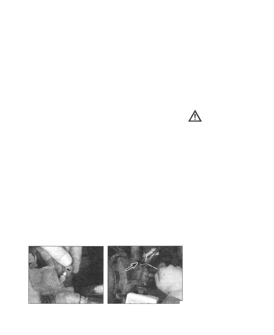
14 Remove the dust cap from the first
caliper's bleed screw. Fit the spanner over the
bleed screw, and push the tube onto the bleed
screw nipple (see illustrations). Place the
other end of the tube in the jar, and pour in
sufficient fluid to cover the end of the tube.
15 Throughout the procedure, keep an eye on
the reservoir fluid level, and ensure that it is
maintained above the "MIN" level line as the
brakes are bled; top it up before starting if
necessary.
16 Have the assistant fully depress the brake
pedal several times to build up pressure - then
on the final downstroke, keep it depressed.
17 While pedal pressure is maintained,
slacken the bleed screw (approximately one
turn) and allow the brake fluid to flow into the
jar. Pedal pressure should be maintained
2.14a Remove the dust cap from the first
caliper's bleed screw (rear left-hand caliper
shown)
J
2.14b Fit the spanner over the bleed screw,
and push the tube onto the bleed screw
nipple
throughout; follow the pedal down to the end
of its travel if necessary, but do not release it.
When the flow stops, tighten the bleed screw
again, then have your assistant release the
pedal slowly. Re-check the reservoir fluid
level, and top it up if necessary.
18 If air is present in the brake lines, it will
appear as bubbles in the expelled fluid.
Repeat the steps given in the two previous
paragraphs, until the fluid emerging from the
bleed screw is free from air bubbles. If the
master cylinder has been drained and refilled,
and air is being bled from the first brake line,
allow approximately five seconds between
cycles for the master cylinder passages to
refill.
19 When no more air bubbles appear, tighten
the bleed screw securely, then remove the
tube and spanner and refit the dust cap.
Caution: Do not over-tighten the
bleed screw.
20 Repeat the procedure on the remaining
brake lines to be bled, until all air is removed
from the system and the brake pedal feels firm
again.
Bleeding - using a one-way valve kit
21 As their name implies, these kits consist of
a length of tubing with a one-way valve fitted,
to prevent expelled air and fluid being drawn
back into the system; some kits include a
translucent container, which can be positioned
so that the air bubbles can be more easily
seen flowing from the end of the tube.
22 The kit is connected to the bleed screw,
which is then opened. The user returns to the
driver's seat, depresses the brake pedal with a
smooth, steady stroke and slowly releases it;
this process is repeated until the expelled fluid
is free of air bubbles.
23 Note that the use of these kits can simplify
the bleed operation so much, that it is easy to
forget the reservoir fluid level. Ensure that it is
maintained at least above the "MIN" level line
at all times, or air may be drawn into the
system.
Bleeding - using a pressure-bleeding
kit
24 These kits are usually powered by the
reservoir of pressurised air contained in the
spare tyre. However, note that it will probably
be necessary to reduce the tyre pressure to a
lower level than normal; refer to the
instructions supplied with the kit.
25 The method involves connecting a
pressurised, fluid-filled container to the master
cylinder reservoir. Bleeding can then be
carried out simply by opening each bleed
screw in turn, and allowing the fluid to flow out
under moderate pressure until no more air
bubbles can be seen in the expelled fluid.
26 This method has the advantage that the
large reservoir of fluid provides an additional
safeguard against air being drawn into the
system during bleeding.
27 Pressure-bleeding is particularly effective
Braking system 9•5
when bleeding "difficult" systems, or when
bleeding the complete system at the time of
routine fluid renewal.
All methods
28 When bleeding is complete, and firm pedal
feel is restored, wash off any spilt fluid, tighten
the bleed screws securely, and refit their dust
caps (where applicable).
29 Check the hydraulic fluid level in the
master cylinder reservoir; top it up if
necessary.
30 Dispose of any hydraulic fluid that has
been bled from the system; it cannot be re-
used. Bear in mind that brake fluid is
poisonous and highly-flammable.
31 Check the feel of the brake pedal. If it feels
at all spongy, it is probable that air is still
present in the system; further bleeding will
therefore be required. If the bleeding
procedure has been repeated several times
and brake feel has still not been restored, the
problem may be caused by worn master
cylinder seals (this is confirmed if excessive air
bubbles are seen in the fluid reservoir as the
brake pedal is depressed). See Section 10 for
a description of the master cylinder overhaul
procedure.
Models with ABS
Note: The front wheel brake circuits must
always be bled before the rear circuit.
Front wheel brake circuits
32 Follow one of the methods described
above for non-ABS models.
Rear wheel brake circuits
33 Top-up the level of fluid in the reservoir to
the "MAX" mark. Maintain the level at least
above the "MIN" mark throughout the bleeding
process.
34 pi* one end of a length of tubing to the rear
brake caliper bleed screw, and immerse the
other end of the tubing in brake fluid,
contained in a clean jar.
35 Have an assistant turn the ignition switch
to the second position, then depress and hold
the brake pedal; this will power the hydraulic
pump and pressurise the rear brake circuit.
36 Using a ring spanner, slacken the caliper
bleed screw by about one turn, and allow
brake fluid to flow through the tube into the jar.
Ensure that pedal pressure is maintained
whilst the bleed screw is open.
Caution: Do not allow the
hydraulic pump to run for more
than two minutes at a time. After
this period, switch off the ignition,
and allow the pump to cool for ten minutes
before restarting. Under no circumstances
must the pump be allowed to run dry.
37 Any air present in the system will be
expelled as bubbles in the brake fluid. When
no more bubbles can be seen escaping,
tighten the bleed screw, release the brake
pedal, and switch off the ignition.
38 Clean off any excess brake fluid from
around the bleed screw, and refit the dust cap.
39 The above process can be repeated at the
other rear wheel caliper, if necessary.
40 When the system has been bled, top-up
the level of fluid in the reservoir to the "MAX"
mark, and refit the cap.
Warning: Brake pads must be
renewed as a complete set, ie
BOTH left and right brake pad
sets must be renewed at the
same time. DO NOT renew the pads on
just one roadwheel, as unbalanced braking
may occur, making the car unstable.
Although standard Saab brake pads do not
contain asbestos, it is still wise to take
safety precautions when cleaning the
brake components. Do not use
compressed air to blow out brake dust and
debris - use a brush. Avoid inhaling any of
the dust; wear an approved filtration mask.
Use only proprietary brake cleaner fluid or
methylated spirit to cleanse the brake
components, DO NOT use petrol or any
other petroleum-based product.
Note: As the handbrake and footbrake
systems are self-adjusting, it is not possible to
assess brake pad wear from the amount of
pedal or lever travel - a visual inspection must
be carried out, as described in Chapter 1.
1 The specification of the Saab 9OOO's front
brakes has been revised during the car's
production life; refer to the Specifications for
details, and establish which components are
fitted to your model.
2 Park the vehicle on a firm, level surface,
then chock the rear wheels and apply the
handbrake. Raise the front of the vehicle, rest
it securely on axle stands, and remove both
front roadwheels - refer to "Jacking, towing
and wheel changing" for guidance.
Pad removal - Girling caliper
3 At the first caliper, use a socket wrench and
spanner to unscrew the lower guide pin bolt.
4 Grasp the hydraulic body of the caliper and
pivot it upwards, taking care not to strain
brake hose or union. Draw out both brake
pads; if they bind against the disc, apply
pressure to the inboard pad with a pair of grips
to retract the piston back into the caliper.
Caution: Keep an eye on the level
in the brake fluid reservoir as you
retract the pads, to ensure that
the displaced fluid does not
cause it to overflow.
5 Remove the pads from the second caliper in
the same manner.
6 Clear the dust and debris from the carrier
surfaces, using a wire brush and brake cleaner
fluid. Avoid inhaling the airborne dust.
7 Examine piston seals for signs of leaking or
deterioration, and the piston itself for signs of
wear or damage.
Pad removal -ATE caliper
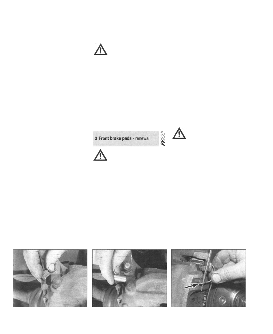
8 At the first caliper, remove the dust caps,
then use a 7 mm hex bit to slacken and
remove the guide pins (see illustrations). '
9 Carefully prise off the spring clip using a
screwdriver (see illustration); support the
caliper hydraulic body as you do this.
10 Take the weight of the hydraulic body, and
lift it away from the carrier. If the pads bind
against the disc, apply pressure to the inboard
pad with a pair of grips to retract the piston
back into the caliper. Remove the inboard
3.8a At the first caliper, remove the dust
caps...
3.8b . . . then use a 7 mm hex bit to slacken
and remove the guide pins
3.9 Carefully prise off the spring clip
(arrowed) using a screwdriver
Нет комментариевНе стесняйтесь поделиться с нами вашим ценным мнением.
Текст