SAAB 9000. Manual — part 22
3•10 Cooling, heating and ventilation systems
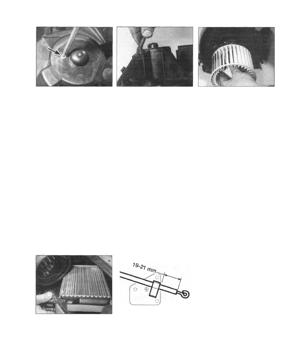
9.29a Unscrew the motor mounting
screw...
illustrations). Note how the two halves fit
together, to facilitate reassembly.
29 Unscrew the motor mounting screw, lift
the lead cover and remove the motor from the
housing (see illustrations).
Refitting
30 Refitting is a reversal of the removal
procedure, but when refitting the false
bulkhead panel, take care not to pull the wiring
from the radiator fan control unit. When
refitting the plastic drainage moulding, make
sure that it locates under the windscreen
moulding lower lip.
Heater matrix
Removal
31 Follow the procedure for removing the
heater blower motor as previously described.
32 If not already done, drain the cooling
system with reference to Chapter 1.
33 If not already done, loosen the clips and
disconnect the hoses from the matrix.
34 Support the evaporator housing as high as
possible, then withdraw the heater matrix from
the heater housing (see illustration). If
necessary, the inlet and outlet stubs can be
removed from the matrix, after removing the
special clips. Recover the O-rings.
35 Examine the O-rings, and if necessary
renew them.
Refitting
36 Refitting is a reversal of removal. After
reconnecting the hoses and before refitting the
9.29b . . . lift the lead cover...
remaining components, refill the cooling
system and check for leaks.
Heater box
Removal
37 Remove the heater blower motor and the
matrix as described previously in this Section.
38 Remove the facia panel assembly as
described in Chapter 11.
39 Remove the panel vents, air ducts, and the
left-hand defroster vent, then disconnect the
right-hand defroster vent.
40 Remove the air duct for the rear seat
passengers from the heater box.
41 Disconnect the wiring for the servo motor
and heater blower motor from the heater box.
42 Unscrew the heater box mounting bolts.
43 Unclip the wiring loom in the engine
compartment, and pull the rubber grommet to
one side.
44 Withdraw the heater box diagonally
upwards. Note that the bottom of the heater
box locates in a groove on the bulkhead and
facia panel assembly.
Refitting
45 Refitting is a reversal of removal.
Heater control panel (except
ACC models)
Removal
46 Remove the glovebox with reference to
Chapter 11. Also remove the panel beneath
the glovebox.
47 Reach up behind the heater control panel,
H 28531
9.34 Removing the heater matrix from the
heater housing
9.57 Heater temperature control cable
refitting dimension
9.29c ... and remove the motor from the
housing
and release the four clips. Pull out the panel.
48 Disconnect the air distribution valve link
rod, the bevel gear for the temperature control
valve, and all connectors.
Refitting
49 Refitting is a reversal of removal, but note
the following points:
a) When refitting the bevel gear for the
temperature control valve, make sure that
the valve In the engine compartment (as
well as the control knob) is set to COLD.
b) When refitting the link rod, turn the pinion
spindle anti-clockwise as far as possible,
then set the air distribution control to
position "O". Reconnect the link rod so
that the orange part is towards the spindle
on the control panel.
c) Check the operation of the heater controls
on completion.
Heater temperature control cable
Removal
50 Remove the glovebox as described in
Chapter 11. Also remove the panel from under
the glovebox.
51 Remove the speaker grilles, then unscrew
the screws from the top of the facia panel by
prising up the front edge, and pulling it
forwards so that the clip is released from the
rear edge.
52 Unscrew the screws and lower the power
distribution panel, then remove the side vent
and defroster air ducts.
53 Reach up behind the heater control panel
and release the clips. Pull the panel forwards.
54 Disconnect the air distribution valve link
rod, and disconnect the bevel gear for the
temperature control cable from the control
panel.
55 Disconnect the inner control cable from
the temperature valve in the engine
compartment.
56 Release the clip securing the cable to the
heater box, and remove the cable.
Refitting
57 Refitting is a reversal of removal, but note
the following points:
a) When reconnecting the cable to the valve
in the engine compartment, position the
outer cable as shown (see illustration).
Cooling, heating and ventilation systems 3•11
b) Refer to the refitting instructions given in
paragraph 49.
c) Check the operation of the heater controls
on completion.
Climate control unit
Removal
58 Disconnect the battery negative lead.
59 Carefully pull out the ashtray, and leave it
hanging on the wiring.
60 Push out the control panel complete with
the control unit, and disconnect the multi-plug
and earth.
Refining
61 Refitting is a reversal of removal.
Climate control unit sensors
62 The climate control unit sensors are
Iocated as follows. The sun sensor is located
either on the left-hand side of the facia, or on
the top centre of the facia. The ambient air
temperature sensor is located in the inlet air
plenum to the heater assembly, and the
interior air temperature sensor is located
centrally on the facia. The mixed air sensor is
also located centrally in the heater assembly.
Interior air temperature sensor
Removal
63 Disconnect the battery negative lead.
64 Remove the ashtray from the facia panel.
65 Remove the climate control unit as
previously described.
66 Pull out the air sensor, and disconnect the
wiring.
Refitting
67 Refitting is a reversal of removal, but make
sure that the sensor hose is not twisted.
Ambient air temperature sensor
Removal
68 Disconnect the battery negative lead.
69 Working in the engine compartment,
remove the bulkhead panel.
70 Disconnect the wiring and remove the
sensor.
refitting
71 Refitting is a reversal of removal, but make
sure that the metallic surface of the sensor is
facing upwards.
Mixed air sensor
Removal
72 Disconnect the battery negative lead.
73 Remove the glovebox with reference to
Chapter 11.
74 Remove the sensor from the air
distribution housing, and disconnect the
wiring.
Refitting
75 Refitting is a reversal of removal.
Sun sensor
Removal
Note: On later models the sensor was fitted to
the glare shield on the dashboard.
76 Disconnect the battery negative lead.
77 Remove the left-hand speaker grille.
78 Disconnect the wiring, and remove the
sensor from the double-sided tape.
Refitting
79 Clean away all traces of the double-sided
tape, then secure the new sensor with new
tape. The remaining procedure is a reversal of
removal.
Climate control system servo
motors
Removal
80 On the control unit, press the red button
until "HI" appears on the display.
81 Disconnect the battery negative lead.
82 Remove the glovebox as described in
Chapter 11.
83 Unscrew the screws, and lower the power
distribution panel.
84 Disconnect the wiring for the servo
motors, heater blower motor and interior air
sensor.
85 Disconnect the temperature control cable
from the servo motor.
86 Unscrew the mounting screws, and pull
out the bracket complete with the electric
servo motors.
87 Disconnect the hose from the interior air
sensor, and lift out the bracket complete with
the motors.
Refitting
88 Pull out the control panel slightly from the
facia, then refit the bracket with motors,
making sure that the bevel gear is correctly
located, and that the cable is reconnected on
the correct side of the bracket. Insert and
tighten the mounting screws.
89 Reconnect the wiring, and connect the
hose to the interior air sensor.
90 Refit the power distribution panel, and
tighten the screws.
91 Refit the glovebox with reference to
Chapter 11.
92 Reconnect the battery negative lead.
Rear door air circulator blower
motors
Removal
93 Remove the rear door interior trim panel,
with reference to Chapter 11.
94 Disconnect the wiring, then unscrew the
mounting screws and remove the motor from
inside the door.
Refitting
95 Refitting is a reversal of removal.
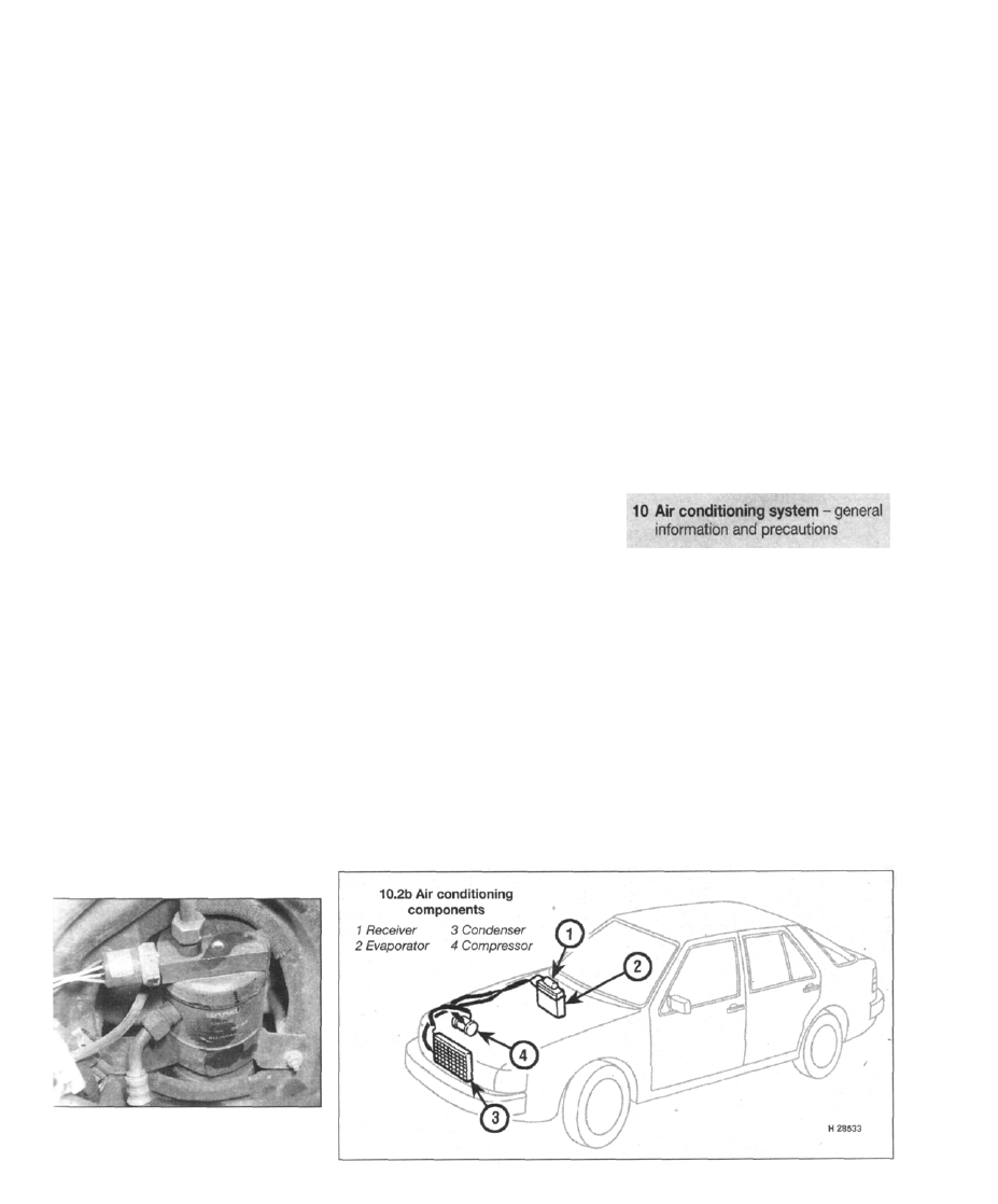
10.2a Air conditioning receiver is located in
the front right-hand corner of the engine
compartment (later models)
General information
1 Air conditioning is available on certain
models. It enables the temperature of air
inside the car to be lowered, and also
dehumidifies the air, which makes for rapid
demisting and increased comfort.
2 The cooling side of the system works in the
same way as a domestic refrigerator.
Refrigerant gas is drawn into a belt-driven
compressor, and passes into a condenser
mounted in front of the radiator, where it loses
heat and becomes liquid. The liquid passes
through a receiver and expansion valve to an
evaporator, where it changes from liquid under
high pressure to gas under low pressure. This
change is accompanied by a drop in
temperature, which cools the evaporator. The
refrigerant returns to the compressor, and the
cycle begins again (see illustrations).
3•12 Cooling, heating and ventilation systems
3 On certain non-UK models fitted with
automatic climate control (ACC), a separate
evaporator and fan unit is located in the boot.
4 Air drawn through the evaporator passes to
the air distribution unit. The air conditioning
system has two control buttons located to the
left of the heater control panel - one button
switches the air conditioning on, and the other
operates the interior air recirculation system.
5 The heating side of the system works in the
same way as on models without air
conditioning (see Section 8).
6 The operation of the system is controlled by
an electromagnetic clutch on the compressor
drive pulley. Any problems with the system
should be referred to a Saab dealer.
7 The air conditioning compressor will not
operate if refrigerant pressure is below a
satisfactory level.
Precautions
8 When working on the air conditioning
system, it is necessary to observe special
precautions. If for any reason the system must
be disconnected, entrust this task to your
Saab dealer or a refrigeration engineer.
Warning: The refrigeration circuit
contains a liquid refrigerant under
pressure, and it is therefore
dangerous to disconnect any part of the
system without specialised knowledge and
equipment. The refrigerant is potentially
dangerous, and should only be handled by
qualified persons. If it is splashed onto the
skin, it can cause frostbite. It is not itself
poisonous, but in the presence of a
naked flame (including a cigarette) it
forms a poisonous gas. Uncontrolled
discharging of the refrigerant is
dangerous, and potentially damaging to
the environment. Do not operate the air
conditioning system if it is known to be
short of refrigerant, as this may damage
the compressor.
Warning: Do not attempt to open
the refrigerant circuit. Refer to
the precautions given in
Section 10.
1 The only operation which can be carried out
easily without discharging the refrigerant is
renewal of the compressor drivebelt. This is
described in Chapter 1, Section 22. All other
operations must be referred to a Saab dealer
or an air conditioning specialist.
2 If necessary for access to other
components, the compressor can be
unbolted and moved aside, without
disconnecting its flexible hoses, after
removing the drivebelt.
3 Access to the condenser is gained by
removing the radiator (and, where applicable,
the intercooler).
4A•1
Chapter 4 Part A: Fuel and exhaust systems
Contents
Accelerator cable - removal, refitting and adjustment 3
Accelerator pedal - removal and refitting 4
Air cleaner assembly - removal and refitting 2
Cruise control system - description and component renewal 5
Exhaust manifold - removal and refitting 21
Exhaust system - general information and component removal. 22
Fuel gauge sender unit (LH-Jetronic models) - removal
Fuel injection system general information 8
Fuel injection system - precautions and depressurisation 9
Fuel injection system - testing, checking and adjustment 14
Fuel injection system components (LH-Jetronic) - removal
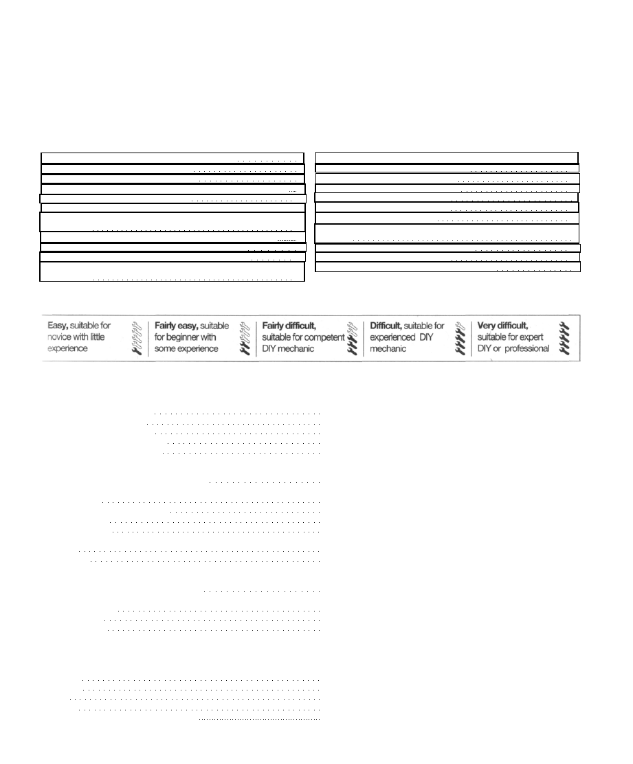
Degrees of difficulty
Fuel injection system components (Trionic) - removal and refitting . 16
Fuel pump - testing, removal and refitting 10
Fuel pump relay - testing and renewal 11
Fuel tank - removal, repair and refitting 13
General information and precautions 1
Inlet manifold - removal and refitting 20
Intercooler - removal and refitting 19
Traction control system (TCS) - description and component
Turbocharger - description and precautions 17
Turbocharger - removal and refitting 18
Unleaded petrol - general information and usage 7
Specifications
System type
1985 cc models (1986 to 1993) LH-Jetronic fuel injection system
1985 cc models (1994-on) Saab Trionic SFi engine management system
2290 cc models (1990 to 1992) LH-Jetronic fuel injection system
2290 cc non-Turbo models (1993) LH-Jetronic fuel injection system
2290 cc Turbo models (1993-on) Saab Trionic SFi engine management system
Fuel system data (LH-Jetronic fuel injection system)
Auxiliary air valve winding resistance (at 20°C) 40 to 60 ohms
Idle air control valve resistance (at 20°C):
LH version 2.2 20 ± 5 ohms
LH version 2.4, LH version 2.4.1 7 ± 5 ohms
LH version 2.4.2 12 ± 3 ohms
Fuel pump capacity 900 cc/30 sec (minimum)
Fuel gauge sender unit winding resistance:
Full tank 350 ohms
Empty tank 35 ohms
Idle speed:
LH-Jetronic fuel injection system without automatic idle control (AIC).. 850 ± 75 rpm
LH-Jetronic fuel injection system with AIC Controlled by AIC valve at 850 ± 50 rpm (not adjustable)
Idle mixture CO content:
B202 Turbo (1985) 1.3 ± 0.3 %
B2O2i (1986-on) 1.0 ± 0.5 %
B234i (1991-on) 1.0 ± 0.5 %
Fuel system data (Trionic engine management system)
Manifold absolute pressure sensor (expressed in absolute pressure):
Pressure Voltage (approx)
-0.75
bar 0.48
-0.50
bar 0.95
0
bar 1.9
0.25 bar 2.4
0.50 bar 2.8
0.75 bar . . . . . . . . . . . . . . . . . . . . . . . ... 3.3
Нет комментариевНе стесняйтесь поделиться с нами вашим ценным мнением.
Текст