Chrysler Le Baron, Dodge Dynasty, Plymouth Acclaim. Manual — part 220
semblies. This sensor when emitting a sound signals
that brake lining may need inspection and/or re-
placement.
SHOE AND LINING WEAR
If a visual inspection does not adequately deter-
mine the condition of the lining, a physical check
will be necessary. To check the amount of lining
wear, remove the wheel and tire assemblies, and the
calipers.
Remove the shoe and lining assemblies. (See Brake
Shoe Removal paragraph).
Combined shoe and lining thickness should be
measured at the thinnest part of the assembly.
When a shoe and lining assembly is worn to a
thickness of approximately 7.95 mm (5/16 inch) it
should be replaced.
Replace both shoe assemblies (inboard and out-
board) on the front wheels. It is necessary that both
front wheel sets be replaced whenever shoe assem-
blies on either side are replaced.
If a shoe assembly does not require replacement.
Reinstall, the shoe assemblies making sure each shoe
assembly is returned to the original position. (See
Brake Shoe Installation).
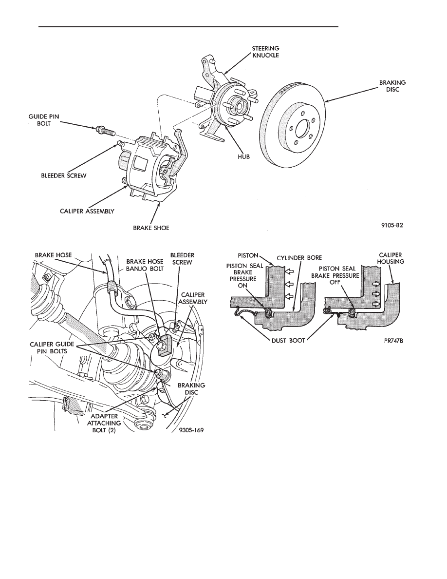
Fig. 4 Disc Brake Caliper Mounting (Non-Family Caliper)
Fig. 5 Disc Brake Caliper Mounting (Typical)
Fig. 6 Piston Seal Function for Automatic
Adjustment
Ä
BRAKES
5 - 33
SERVICE PRECAUTIONS
WARNING: DUST AND DIRT ON BRAKE PARTS
GENERATED DURING THE NORMAL USE AND
WEAR OF MOTOR VEHICLE BRAKE SYSTEMS CAN
CONTAIN ASBESTOS FIBERS. BREATHING EXCES-
SIVE CONCENTRATIONS OF ASBESTOS FIBERS
CAN CAUSE SERIOUS BODILY HARM, SUCH AS
ASBESTOSIS
AND
CANCER.
EXTREME
CARE
SHOULD
BE
EXERCISED
WHILE
SERVICING
BRAKE ASSEMBLIES OR COMPONENTS.
DO NOT CLEAN BRAKE ASSEMBLIES OR COM-
PONENTS WITH COMPRESSED AIR OR BY DRY
BRUSHING; USE A VACUUM CLEANER SPECIFI-
CALLY RECOMMENDED FOR USE WITH ASBES-
TOS FIBERS. IF A SUITABLE VACUUM CLEANER IS
NOT AVAILABLE, CLEANING SHOULD BE DONE
WET USING A WATER DAMPENED CLOTH.
DO NOT CREATE DUST BY SANDING, GRINDING,
AND/OR SHAVING BRAKE LININGS OR PADS UN-
LESS SUCH OPERATION IS DONE WHILE USING
PROPERLY EXHAUST VENTILATED EQUIPMENT.
DISPOSE OF ALL DUST AND DIRT SUSPECTED
TO CONTAIN ANY ASBESTOS FIBERS IN SEALED
BAGS OR CONTAINERS TO MINIMIZE DUST EXPO-
SURE TO YOURSELF AND OTHERS.
FOLLOW ALL RECOMMENDED PRACTICES PRE-
SCRIBED BY THE OCCUPATIONAL SAFETY AND
HEALTH ADMINISTRATION AND THE ENVIRONMEN-
TAL PROTECTION AGENCY. FOR THE HANDLING,
PROCESSING, AND DISPOSITION OF DUST OR DIRT
WHICH MAY CONTAIN ASBESTOS FIBERS.
IT IS RECOMMENDED NOT TO BREATH ANY TYPE
OF BRAKE LINING MATERIAL DUST EVEN ASBES-
TOS FREE, DUE TO THE FIBROUS NATURE OF THE
MATERIALS BEING USED.
Grease or any other foreign material must be kept off
caliper assembly, surfaces of braking disc and external
surfaces of hub, during service procedures.
Handling of the braking disc and caliper. Should be
done in such a way as to avoid deformation of the disc
and scratching or nicking of the brake linings.
If inspection reveals that the square sectioned cali-
per piston seal is worn or damaged, it should be
replaced immediately.
During removal and installation of a wheel and tire
assembly, use care not to strike the caliper.
Before vehicle is moved after any brake service
work, be sure to obtain a firm brake pedal.
5 - 34
BRAKES
Ä
KELSEY HAYES DOUBLE PIN FAMILY CALIPER
BRAKE SHOE SERVICE PROCEDURES
BRAKE SHOE REMOVAL
(1) Raise vehicle on jackstands or centered on a
hoist. See Hoisting Information in the Lubrication
and Maintenance section of this manual.
(2) Remove front wheel and tire assemblies.
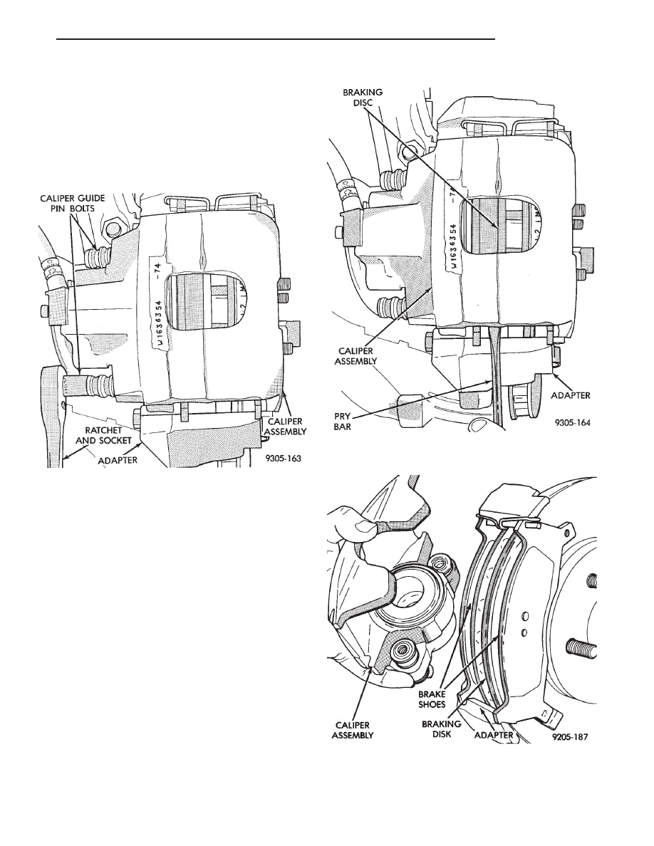
(3) Remove caliper guide pin bolts (Fig. 1).
(4) After removing caliper guide pin bolts. Lift cal-
iper away from braking disc using a pry bar or
screwdriver (Fig. 2).
(5) Remove caliper assembly from braking disc and
adapter by sliding the assembly out and away from
the braking disc and adapter (Fig. 3).
(6) Support caliper firmly to prevent weight of cal-
iper from damaging the flexible brake hose (Fig. 4).
(7) Remove the outboard brake shoe assembly from
the caliper adapter (Fig. 5).
(8) Remove the braking disk (rotor) from the hub
by pulling it straight off the wheel mounting studs
(Fig. 6).
Fig. 1 Removing or Installing Caliper Guide Pin
Bolts
Fig. 2 Loosening Family Caliper Assembly From
Adapter And Rotor
Fig. 3 Removing or Installing Caliper Assembly
Ä
BRAKES
5 - 35
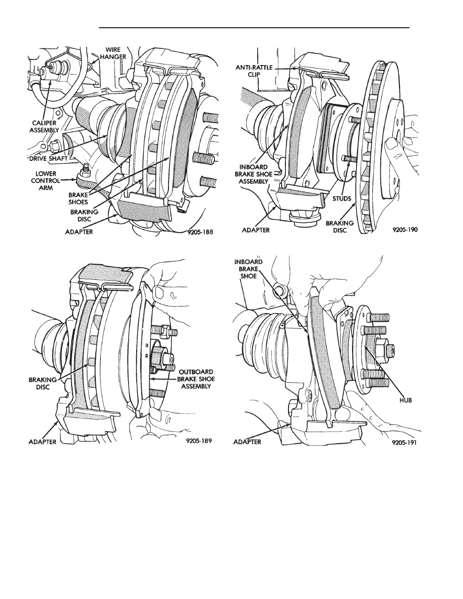
(9) Remove the inboard brake shoe assembly by
sliding it out along the bottom adapter abutment un-
til brake shoe assembly loosens from anti-rattle clip
(Fig. 7).
(10) Remove the anti-rattle clip from the top
adapter abutment (Fig. 8).
BRAKE SHOE INSTALLATION
(1) Thoroughly clean and lubricate both adapter
abutments with a liberal amount of Mopar
t Multi-
purpose Lubricant, or equivalent.
(2) Install the anti-rattle clip on the upper abut-
ment of the caliper mounting adapter (Fig. 8).
(3) Install the new inboard brake shoe assembly on
the adapter by sliding it along the adapter abut-
ments. Be careful not to get any grease from the
adapter abutment on the surface of the brake lining
Fig. 4 Storing Caliper
Fig. 5 Removing and Installing Outboard Shoe
Assembly
Fig. 6 Removing or Installing Braking Disc
Fig. 7 Removing or Installing Inboard Shoe
Assembly
5 - 36
BRAKES
Ä
Нет комментариевНе стесняйтесь поделиться с нами вашим ценным мнением.
Текст