Chrysler Le Baron, Dodge Dynasty, Plymouth Acclaim. Manual — part 39
THROTTLE BODY MINIMUM AIR FLOW CHECK
PROCEDURE
(1) Warm engine in Park or neutral until the cooling
fan has cycled on and off at least once.
(2) Hook-up timing check device and Tachometer.
(3) Disconnect the coolant temperature sensor and
set basic timing to 12° BTDC
6 2° BTDC.
(4) Shut off engine. Connect harness connector to
coolant temperature sensor.
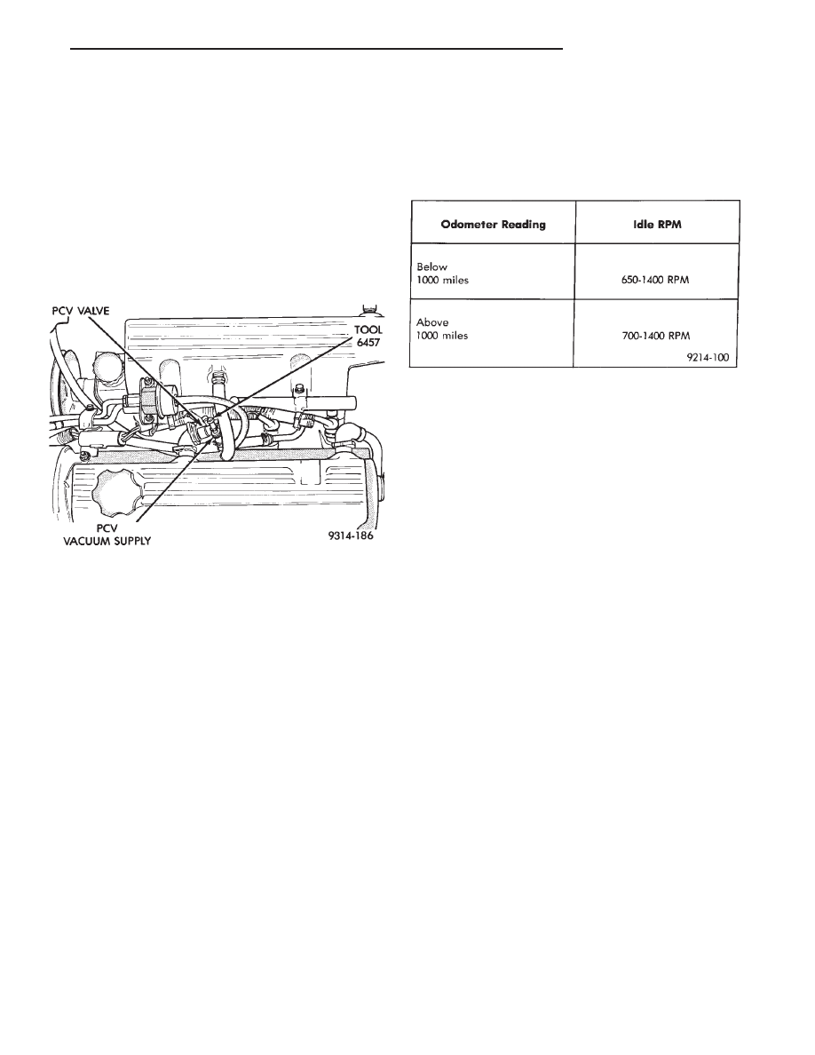
(5) Disconnect the PCV valve hose from the nipple
on the intake manifold.
(6) Attach Air Metering Fitting #6457 (0.125 in.
orifice) to the intake manifold PCV nipple (Fig. 2).
(7) Connect DRBII scan tool to the data link connec-
tor. The connector is located next to the powertrain
control module (PCM) (Fig. 1).
(8) Restart engine. Allow engine to idle for at least
one minute.
(9) Using the DRBII scan tool, access Min. Airflow
Idle Spd. The following will then occur:
• idle air control motor fully closes
• Idle spark advance becomes fixed
• The DRBII scan tool displays engine RPM
(10) Check idle RPM with tachometer, if idle RPM is
within the specifications then the throttle body mini-
mum airflow is set correctly.
If the idle RPM is not within specification, replace
the throttle body.
(11) Shut off engine.
(12) Remove Air Metering Fitting #6457 from the
intake manifold PCV nipple. Reinstall the PCV valve
hose.
(13) Remove DRBII scan tool.
(14) Disconnect timing light and tachometer.
IGNITION TIMING PROCEDURE
Refer to Group 8D Ignition System.
POWERTRAIN CONTROL MODULE 60-WAY CON-
NECTOR
Check the powertrain control module (PCM) 60-way
connector for the following.
• Spread terminals
• Stretched or pulled out wires
• Undertightened or overtightened 60 way connector
Tighten the PCM connector to 4 N
Im (35 in. lbs.)
torque. When checking terminal pin outs, refer to the
Powertrain Control Module 60-Way Connector Dia-
gram for circuit wire colors and cavity numbers.
Fig. 2 Checking Minimum Air Flow Using Special
Tool 6457
IDLE SPECIFICATIONS
Ä
FUEL SYSTEMS
14 - 73

POWER
TRAIN
CONTROL
MODULE
60-W
A
Y
CONNECTOR
14 - 74
FUEL SYSTEMS
Ä

DIAGNOSTIC TROUBLE CODE DESCRIPTION
Ä
FUEL SYSTEMS
14 - 75

DIAGNOSTIC TROUBLE CODE DESCRIPTION (CONTINUED)
14 - 76
FUEL SYSTEMS
Ä
Нет комментариевНе стесняйтесь поделиться с нами вашим ценным мнением.
Текст