Chrysler Le Baron, Dodge Dynasty, Plymouth Acclaim. Manual — part 172
AP-VEHICLE BODY COMPONENT SERVICE
INDEX
page
page
A-Pillar and Roof Rail Mouldings
B-Pillar Trim Panel—AP-44 Body
Body Side Moulding and Applique
Cowl Panel Trim and Scuff Plates
. . . . . . . . . . . . . . . 107
. . . . . . . . . . . . . . . . . . . . . . . . . . . 113
. . . . . . . . . . . . . . . . . . . . 113
. . . . . . . . . . . . . . . . . . . . 100
Front Door Belt Moulding and Weatherstrip
. . . . . . . . . . . . . . . . . . . . . . . . 101
Front Door Glass Channel and Run
. . . . . . . . . . . . . . . . . . . . . . . . . . 103
Front Door Glass Run Lower Channels
. . . . . . . . . . . . . . . . . . . . . . . . 101
. . . . . . . . . . . . . . . 101
Front Door Trim Panel—AP-24/44 Body
. . . . . . . . . . . . . . . . . . 100
Front Door Window Regulator/Manual
Front Door Window Regulator/Power
. . . . . . . . . . . . . . . . . . 99
Front Power Door Lock Actuator
. . . . . . . . . . . . . . 110
. . . . . . . . . . . . . . 110
. . . . . . . . . . . . . . . . . . . . . . . . . . . . 111
. . . . . . . . . . . . . . . . . . . . . . . . . . . . . . . . . . 97
. . . . . . . . . . . . . . . . . . . . . . 97
. . . . . . . . . . . . . . . . . . . . . . . . . . . . 114
. . . . . . . . . . . . . . . . . . . . . . . . 97
. . . . . . . . . . . . . . 98
. . . . . . . . . . . . . . . . . . . 116
Lift Gate Remote Release Cable
Lower Quarter Trim Panel—AP-44 Body
Outside Front Door Latch Release Handle
Outside Rear Door Latch Release Handle
. . . . . . . . . . . . . . . . . . . . . . . 113
. . . . . . . . . . . . . . . . 108
. . . . . . . . . . . . . . . . . . . 108
. . . . . . . . . . . . . . . . . . . . 104
Rear Door Belt Moulding and Weatherstrip
. . . . . . . . . . . . . . . . . . . . . . . . 106
Rear Door Glass Run Weatherstrip
. . . . . . . . . . . . . . . . . . . . . . . . 105
Rear Door Silencer and Water Shield
. . . . . . . . . . . . . . . . 107
. . . . . . . . . . . . . . . . . . . . 104
Rear Door Window Regulator/Manual
Rear Door Window Regulator/Power
. . . . . . . . . . . . . . . . . . . . . . . . . 111
. . . . . . . . . . . . . . . . . . . . . . . . . . . . 112
. . . . . . . . . . . . . . . . . . . . . . 115
. . . . . . . . . . . . . . . . . . . 114
. . . . . . . . . . . . . . . . . . . . 115
. . . . . . . . . . . . . . . . . . . 114
Upper Quarter Trim Panel—AP-44 Body
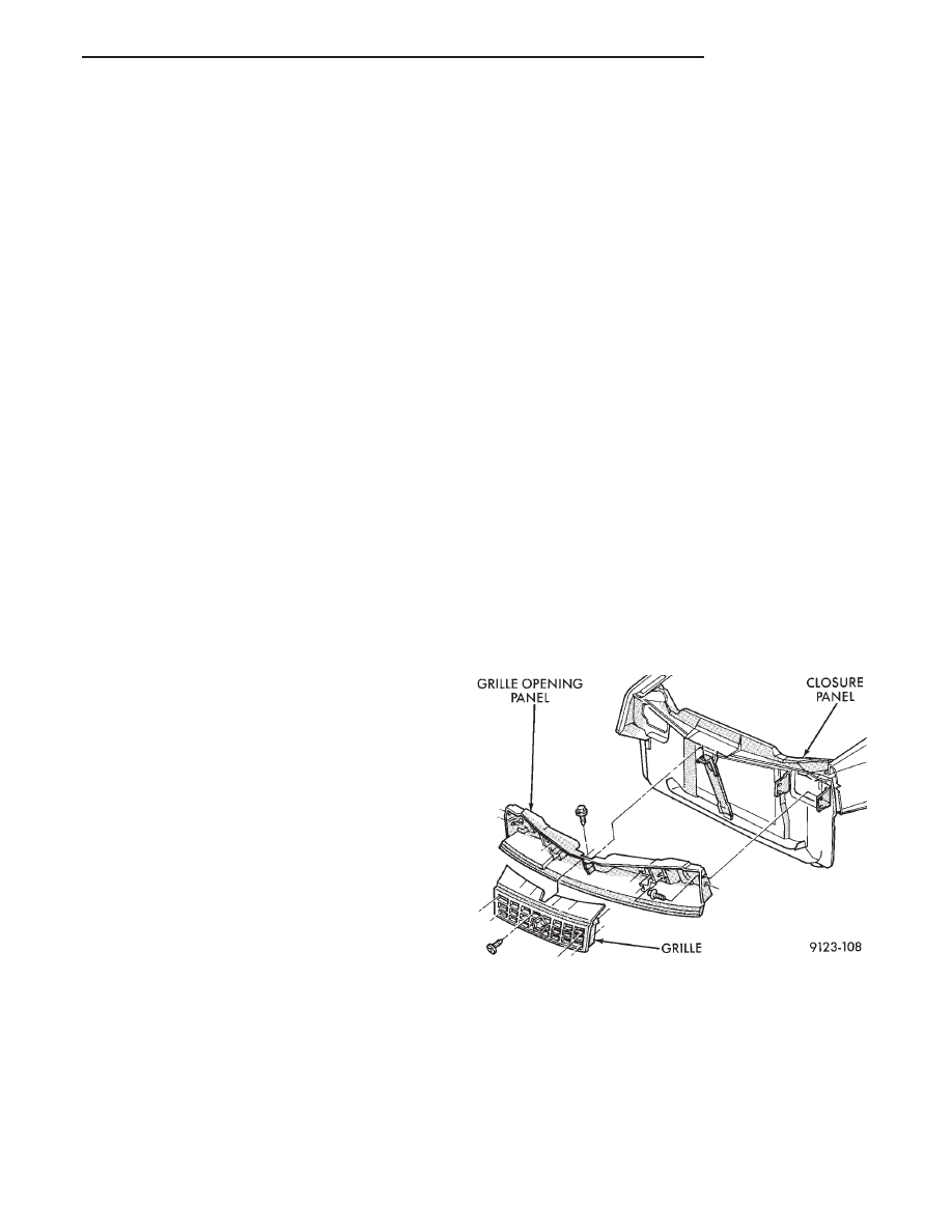
GRILLE
REMOVAL (FIG. 1)
(1) Raise hood to the up position.
(2) Remove screws holding grille to grille opening
panel.
(3) Separate grille from vehicle.
INSTALLATION
Reverse the preceding operation.
GRILLE OPENING PANEL
REMOVAL (FIG. 1)
(1) Remove grille from grille opening panel.
(2) Remove headlamp assemblies. Refer to Group
8L. Lamps for proper procedures.
(3) Remove bolts holding grille opening panel to
closure panel brackets.
(4) Remove bolt holding grille opening panel to
brace in front of radiator.
(5) Separate grille opening panel from vehicle.
INSTALLATION
Reverse the preceding operation.
HOOD AND HINGES
HOOD REMOVAL (FIG. 2)
(1) Raise hood to full up position.
(2) Disconnect the under hood lamp wire connec-
tor.
(3) Mark all bolt and hinge attachment locations
with a grease pencil or other suitable device to pro-
vide reference marks for installation. When install-
Fig. 1 Grille and Grille Opening Panel
Ä
AP-BODY
23 - 97
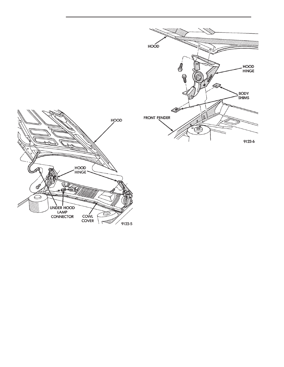
ing hood, align all marks and secure bolts. The hood
should be aligned to 4 mm (0.160 in.) gap to the front
fenders and flush across the top surfaces along fend-
ers.
(4) Remove the top hood to hinge attaching bolts
and loosen the bottom bolts until they can be re-
moved by hand.
(5) With assistance of a helper at the opposite side
of the vehicle to support the hood, remove the bottom
hood to hinge attaching bolts. Separate the hood
from the vehicle.
HOOD INSTALLATION
Reverse the preceding operation.
HOOD HINGE REMOVAL (FIG. 3)
(1) Support hood on the side that requires hinge
replacement.
(2) Mark all bolt and hinge attachment locations
with a grease pencil or other suitable device to pro-
vide reference marks for installation. When install-
ing hood hinge, align all marks and secure bolts. The
hood should be aligned to 4 mm (0.160 in.) gap to the
front fenders and flush across the top surfaces along
fenders. Shims can be added or removed under hood
hinge to achieve proper hood height.
(3) Remove hood to hinge attaching bolts.
(4) Remove hood hinge to front fender attaching
bolts and separate hinge from vehicle.
HOOD HINGE INSTALLATION
Reverse the preceding operation. If necessary, paint
new hinge before installation.
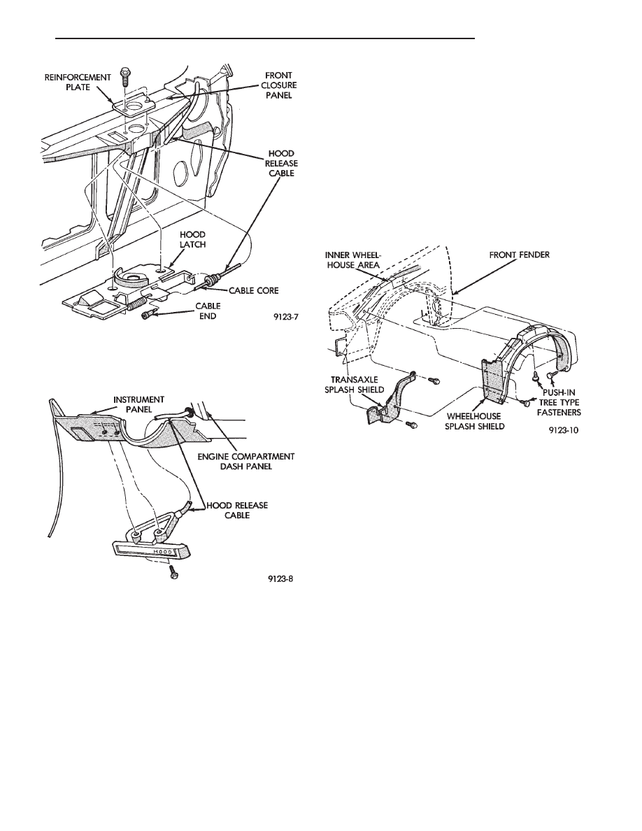
HOOD LATCH AND RELEASE CABLE
HOOD LATCH REMOVAL (FIG. 4)
(1) Raise hood top the full up position.
(2) Remove hood latch attaching bolts holding
latch to radiator closure panel and separate from ve-
hicle.
(3) Pry release cable casing attachment from slot
receiver on latch, disengage cable end from latch arm
hook.
HOOD LATCH INSTALLATION
Reverse the preceding operation.
HOOD LATCH RELEASE CABLE REMOVAL
(FIG. 5)
(1) Raise hood to the full up position.
(2) Remove push-in fasteners holding hood latch
cover to radiator closure panel and separate cover
from vehicle.
(3) Disconnect hood release cable casing and cable
end from hood latch assembly. Refer to Hood Latch
Removal procedure in this section.
(4) Remove hood latch release cable handle attach-
ing bolts from under left lower edge of instrument
panel.
(5) Disengage release cable rubber grommet from
engine compartment dash panel behind instrument
panel.
(6) Rout cable assembly through engine compart-
ment around battery, under fender lip, under relay
bank, and under wiring harnesses, toward dash
panel. Push cable through access hole in dash panel
under the brake master cylinder, into passenger com-
partment.
Fig. 2 Hood Assembly—Typical
Fig. 3 Hood Hinge Assembly
23 - 98
AP-BODY
Ä
HOOD LATCH RELEASE CABLE
INSTALLATION
Reverse the preceding operation.
FRONT END SPLASH SHIELDS
FRONT WHEELHOUSE SPLASH SHIELD
REMOVAL (FIG. 6)
(1) Hoist vehicle and support on suitable safety
stands.
(2) Remove front wheel assembly.
(3) Remove push-in fasteners holding front wheel-
house splash shield to fender opening lip and inner
wheelhouse area.
(4) Separate wheelhouse splash shield from vehi-
cle.
FRONT WHEELHOUSE SPLASH SHIELD
INSTALLATION
Reverse the preceding operation.
TRANSAXLE SPLASH SHIELD REMOVAL (FIG.
6)
(1) Remove one front wheelhouse splash shield
push-in fastener and separate wheelhouse splash
shield from transaxle splash shield.
(2) Remove transaxle splash shield attaching bolts
and separate transaxle splash shield from vehicle.
TRANSAXLE SPLASH SHIELD INSTALLATION
Reverse the preceding operation.
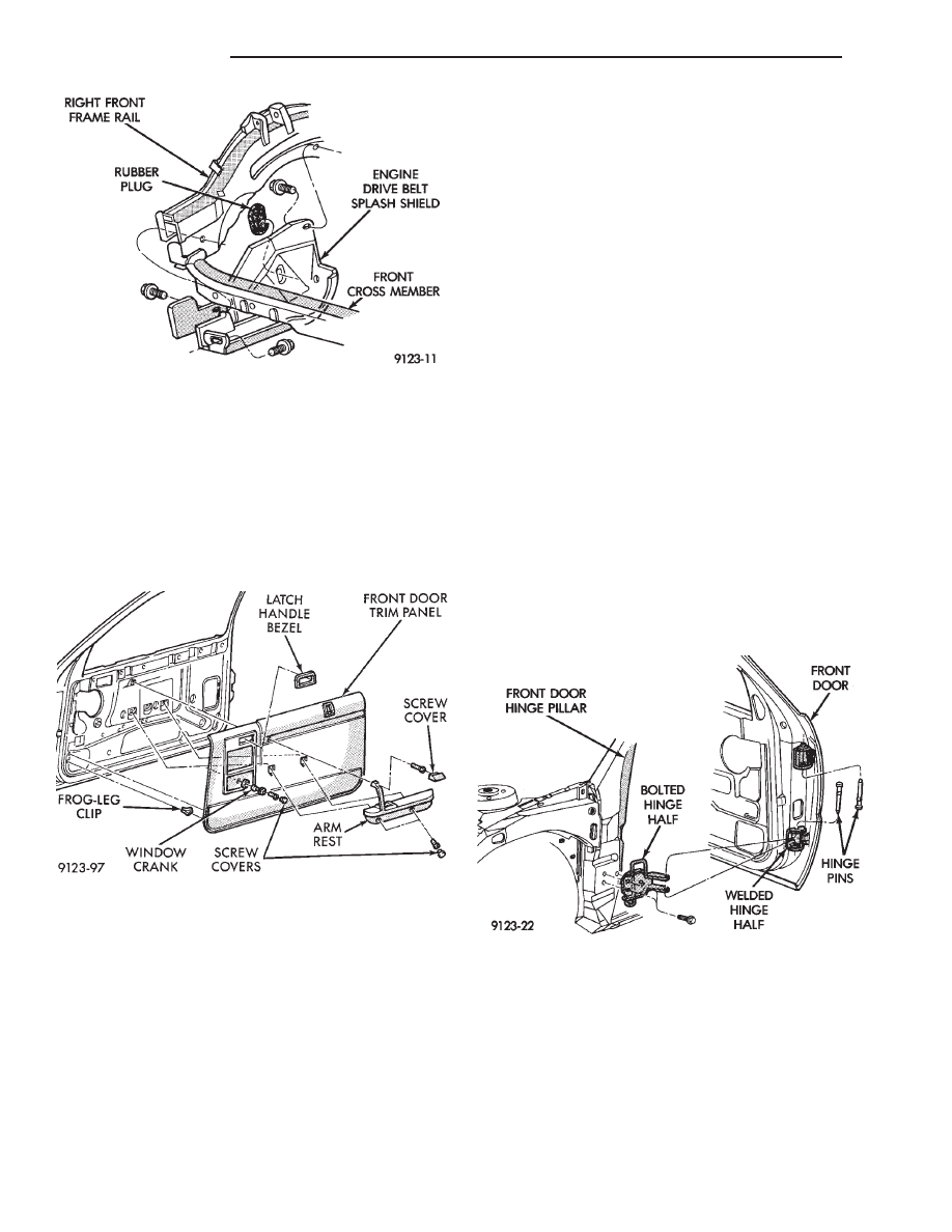
ENGINE DRIVE BELT SPLASH SHIELD
REMOVAL (FIG. 7)
(1) Hoist vehicle and support on suitable safety
stands.
(2) Remove bolts holding engine drive belt splash
shield to right frame rail.
(3) Separate drive belt splash shield from vehicle.
ENGINE DRIVE BELT SPLASH SHIELD
INSTALLATION
Reverse the preceding operation.
FRONT DOOR TRIM PANEL—AP-24/44 Body
DOOR TRIM PANEL REMOVAL (FIG. 8)
(1) Move glass to down position.
(2) Disconnect battery negative cable.
(3) Remove inside latch release handle bezel. Pull
outward at forward edge and push bezel rearward.
(4) Remove screw cover from window crank. Re-
move screw holding crank to regulator and separate
crank from door, if equipped.
(5) Remove remote control mirror bezel.
(6) Remove screw covers from arm rest.
Fig. 4 Hood Latch—Typical
Fig. 5 Hood Latch Release Cable—Typical
Fig. 6 Front Wheelhouse and Transaxle Splash
Shields
Ä
AP-BODY
23 - 99
(7) Remove screws holding arm rest to door trim.
Disconnect power door lock switch wire connector.
(8) Disengage frog-leg clips from around bottom
and side edges of trim panel. Lift trim panel upward
and separate trim from door.
(9) Disconnect courtesy lamp wire connector.
DOOR TRIM PANEL INSTALLATION
Reverse the preceding operation.
FRONT DOOR WATER SHIELD
REMOVAL
(1) Remove front door trim panel.
(2) Remove push-in fasteners holding silencer pad
to door inner panel and separate silencer from door.
(3) Pull water shield from adhesive around perim-
eter of door inner panel.
INSTALLATION
Reverse the preceding operation.
FRONT DOOR AND HINGE
The front door hinge is welded to the door and
bolted to the hinge pillar. The door half of the hinge
pivots on a removable hinge pin. The hinge pin is
driven in from the bottom on the top hinge and from
the top on the bottom hinge. All adjustments to the
hinge are performed on the hinge pillar half of the
hinge. If the welded half of the hinge must be bent to
align door, consult an authorized body repair facility.
FRONT DOOR REMOVAL (FIG. 9)
(1) Remove door trim panel, silencer pad, and wa-
ter shield.
(2) Disconnect all wire connectors and wire har-
ness hold downs inside door and push wire harness
through access hole in front of door into hinge pillar
opening.
(3) Open door and support door on a suitable lift-
ing device.
(4) Drive bottom hinge pin upward and remove pin
from hinge.
(5) Drive top hinge pin downward and remove pin
from hinge.
FRONT DOOR INSTALLATION
Reverse the preceding operation. The door should
not require re-alignment. If door does need align-
ment, refer to Front Door Hinge Installation para-
graph in this section.
FRONT DOOR HINGE REMOVAL (FIG. 9)
(1) Remove front fender wheelhouse splash shield.
Refer to Front Wheelhouse Splash Shield Removal
paragraph in this section.
(2) Support door on a suitable lifting device.
(3) Drive out hinge pin on the effected hinge.
(4) Remove bolts holding hinge to hinge pillar and
separate hinge form vehicle.
Fig. 7 Engine Drive Belt Splash Shield
Fig. 8 Front Door Trim Panel
Fig. 9 Front Door Hinges—Typical
23 - 100
AP-BODY
Ä
Нет комментариевНе стесняйтесь поделиться с нами вашим ценным мнением.
Текст