Chrysler Le Baron, Dodge Dynasty, Plymouth Acclaim. Manual — part 211

These systems do not allow EGR at idle. The 2.2L/
2.5L EGR systems operate at all temperatures. The
3.0L, 3.3L and 3.8L EGR systems do not operate
when coolant temperature is below 4.5°C (40°)F at
start-up. These systems activate when coolant tem-
perature reaches 77°C (170°F).
EGR SYSTEM ON-BOARD DIAGNOSTICS
The powertrain control module (PCM) performs an
on-board diagnostic check of the EGR system on all
California vehicles with EGR systems. The diagnos-
tic system uses the Electric EGR Transducer (EET)
for the system tests.
The diagnostic check activates only during selected
engine/driving conditions. When the conditions are
met, the PCM energizes the transducer solenoid to
disable the EGR. The PCM checks for a change in
the oxygen sensor signal. If the air-fuel mixture goes
lean, the PCM will attempt to enrichen the mixture.
The PCM registers a fault if the EGR system has
failed or degraded. After registering a fault, the PCM
turns on the malfunction indicator lamp (instrument
panel Check Engine light). The malfunction indicator
lamp indicates the need for immediate service.
If a problem is indicated by the malfunction indicator
lamp and a diagnostic trouble code for the EGR system,
check for proper operation of the EGR system. Use the
System Test, EGR Gas Flow Test and EGR Diagnosis
Chart. If the EGR system tests properly, check the sys-
tem using the DRBII scan tool. Refer to On-Board Di-
agnosis in the General Diagnosis sections of Group 14.
Also, refer to the DRBII scan tool and the appropriate
Powertrain Diagnostics Procedure manual.
EXHAUST GAS RECIRCULATION (EGR) SYSTEM
TEST
WARNING:
APPLY
PARKING
BRAKE
AND/OR
BLOCK WHEELS BEFORE PERFORMING EGR SYS-
TEM TEST.
A failed or malfunctioning EGR system can cause
engine spark knock, sags or hesitation, rough idle,
and/or engine stalling. To ensure proper operation of
the EGR system, all passages and moving parts must
be free of deposits that could cause plugging or stick-
ing. Ensure system hoses do not leak. Replace leak-
ing components.
Inspect hose connections between the throttle body,
intake manifold, EGR solenoid and transducer, and
EGR valve. Replace hardened, cracked, or melted
hoses. Repair or replace faulty connectors.
Check the EGR control system and EGR valve with
the engine fully warmed up and running (engine cool-
ant temperature over 150°F). With the transmission in
neutral and the throttle closed, allow the engine to idle
for 70 seconds. Abruptly accelerate the engine to ap-
proximately 2000 rpm, but not over 3000 rpm. The EGR
valve stem should move when accelerating the engine
(the relative position of the groove on the EGR valve
stem should change). Repeat the test several times to
confirm movement. If the EGR valve stem moves, the
control system is operating normally. If the control sys-
tem is not operating normally, refer to the EGR Diag-
nosis Chart to determine the cause.
EGR GAS FLOW TEST
The following procedure should be used to determine
if exhaust gas is flowing through the EGR system.
Connect a hand vacuum pump to the EGR valve
vacuum motor. With engine running at idle speed,
slowly apply vacuum. Engine speed should begin to
drop when applied vacuum reaches 2.0 to 3.5 inches.
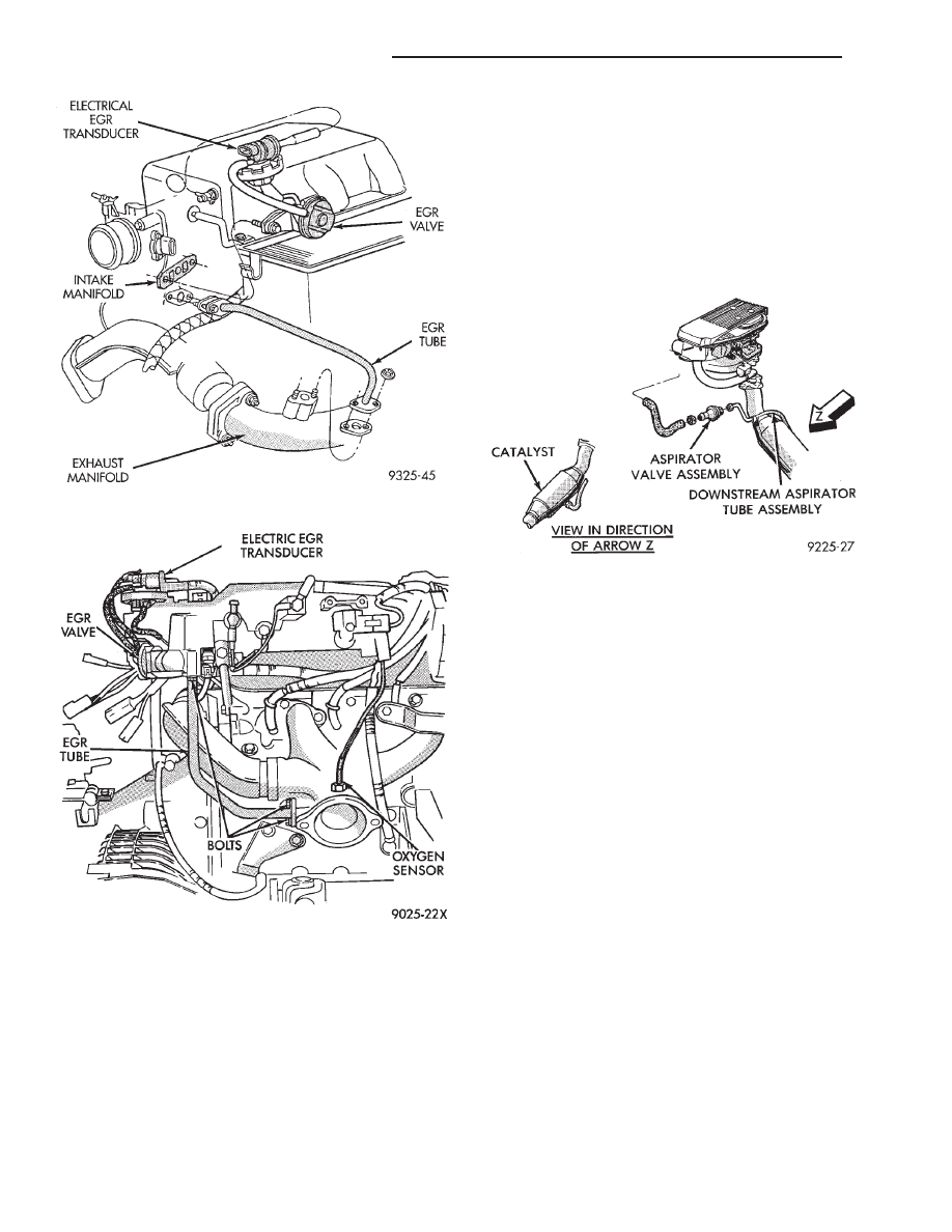
Fig. 14 EGR Mounting—3.3L and 3.8L Engines
Fig. 15 Electric EGR Transducer (EET) Assembly
Ä
EMISSION CONTROL SYSTEMS
25 - 21
Engine speed may drop quickly or engine may even
stall. This indicates that EGR gas is flowing through
the system.
If both the EGR Gas Flow Check, System Check
and Diagnosis Chart are completed satisfactorily,
then the EGR system functions normally.
If engine speed does not drop off when performing
the test, remove both the EGR valve and EGR tube
and check for plugged passages. Also, check the in-
take manifold inlet passage. Clean or replace these
components for restoration of proper flow.
EGR VALVE SERVICE—2.2L AND 2.5L TBI
ENGINES
REMOVAL
(1) Disconnect electrical connector and vacuum
line from the electric EGR transducer (Fig. 12).
(2) Remove EGR valve bolts from intake manifold.
(3) Remove EGR valve from intake manifold.
(4) Clean gasket surface and discard old gasket.
Check for any signs of leakage or cracked surfaces.
INSTALLATION
(1) Assemble EGR valve with new gasket onto the
intake manifold.
(2) Install EGR valve mounting bolts. Tighten to
22 N
Im (200 in. lbs.) torque.
(3) Reconnect vacuum line and electrical connector
to Electric EGR Transducer.
EGR TUBE SERVICE—2.2L AND 2.5L TBI ENGINES
REMOVAL
(1) Remove EGR tube attaching bolts from intake
and exhaust manifolds.
(2) Remove EGR tube.
(3) Clean intake and exhaust manifold gasket sur-
faces and EGR tube flange gasket surfaces. Discard
old gaskets.
(4) Check for signs of leakage or cracked surfaces
on either manifolds or tube. Replace as necessary.
INSTALLATION
(1) Loosely position EGR tube and new gaskets in
place on intake and exhaust manifolds. Install
mounting bolts.
(2) Tighten attaching bolts to 22 N
Im (200 in. lbs.)
torque.
EGR VALVE SERVICE—3.0L ENGINES
REMOVAL
(1) Disconnect the electric and vacuum connectors
from the electric EGR transducer (EET) (Fig. 16).
(2) Remove EGR valve mounting bolts.
(3) Clean all gasket surfaces and discard old gas-
kets. Check for any signs of leakage or cracked sur-
faces. Repair or replace as necessary.
INSTALLATION
(1) Install EGR valve and new gasket on intake
manifold. Tighten mounting bolts to 22 N
Im (200 in.
lbs.) torque.
(2) Connect the electrical and vacuum connectors
to the electric EGR transducer.
EGR TUBE SERVICE—3.0L ENGINES
REMOVAL
(1) Remove EGR tube flange nuts from exhaust
manifold (Fig. 16).
(2) Remove EGR valve nuts at intake manifold
(Fig. 16). Remove EGR tube.
(3) Clean all gasket surfaces and discard old gas-
kets. Check for any signs of leakage or cracked sur-
faces. Repair or replace as necessary.
INSTALLATION
(1) Loosely install the EGR tube on the intake and
exhaust manifolds with new gaskets.
(2) Tighten EGR tube flange bolts at the intake
manifold to 22 N
Im (200 in. lbs.) torque.
(3) Tighten EGR tube to exhaust manifold nuts to
22 N
Im (200 in. lbs.) torque.
EGR VALVE SERVICE—3.3L AND 3.8L ENGINES
REMOVAL
(1) Disconnect vacuum tube from electric EGR
transducer (EET). Inspect vacuum tube for damage
(Fig. 17).
(2) Remove electrical connector from EET.
(3) Remove EGR valve bolts from intake manifold.
(4) Open EGR transducer clip and remove electric
EGR transducer.
(5) Remove EGR valve from intake manifold.
(6) Clean gasket surface and discard old gasket.
Check for any signs of leakage or cracked surfaces.
Repair or replace as necessary.
INSTALLATION
(1) Assemble EGR valve with new gasket onto the
intake manifold.
(2) Install mounting bolts. Tighten bolts to 22 N
Im
(200 in. lbs.) torque.
(3) Install electric EGR transducer in clip with ori-
entation tab in slot and snap closed.
(4) Reconnect vacuum hose and electrical connec-
tor to EET.
EGR TUBE SERVICE—3.3L AND 3.8L ENGINES
REMOVAL
(1) Remove EGR tube attaching bolts from intake
and exhaust manifolds.
(2) Clean intake and exhaust manifold gasket sur-
faces. Discard old gasket.
25 - 22
EMISSION CONTROL SYSTEMS
Ä
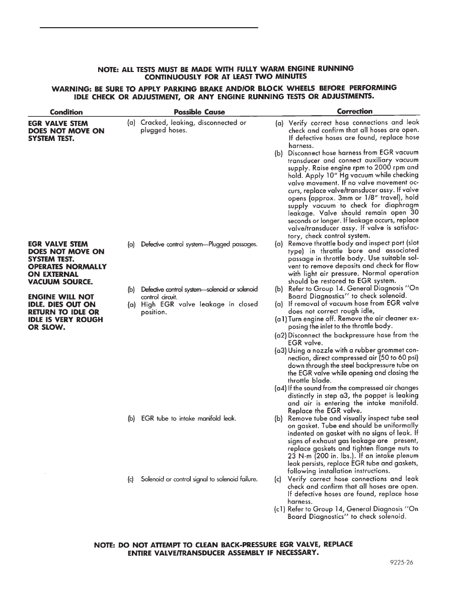
EGR DIAGNOSIS CHART
Ä
EMISSION CONTROL SYSTEMS
25 - 23
(3) Check for signs of leakage or cracked surfaces
on either manifolds or tube. Repair or replace as nec-
essary.
INSTALLATION
(1) Loosely assemble EGR tube and new gaskets
into place on intake and exhaust manifolds.
(2) Tighten mounting bolts to 22 N
Im (200 in. lbs.)
torque.
AIR ASPIRATION SYSTEM
Certain vehicles equipped with the 2.2L or 2.5L
TBI engines have an aspirator valve (Fig. 18). The
valve uses exhaust pressure pulsation to draw fresh
air from the air cleaner into the exhaust system.
This reduces carbon monoxide (CO) and hydrocarbon
(HC) emissions. The aspirator valve works most effi-
ciently at idle and slightly off-idle, where the nega-
tive
pulses
are
strongest.
The
aspirator
valve
remains closed at higher engine speeds.
DIAGNOSIS
The aspirator valve is not repairable. Replace the
valve if it operates incorrectly. Valve failure results
in excessive underhood exhaust system noise at idle
and hardening of the rubber hose from the valve to
the air cleaner. Check for leakage at the aspirator
tube/catalyst assembly joint. Also, inspect the hose
connections at the aspirator valve and air cleaner for
leakage. If the aspirator tube/ catalyst assembly joint
is leaking, tighten the aspirator tube nut to 54 N
Im
(40 ft. lbs) torque. If either hose connection leaks,
and the hose has not hardened, install hose clamps.
To determine if the aspirator valve has failed, dis-
connect the hose from the aspirator inlet. With the
engine at idle in neutral, the negative (vacuum) ex-
haust pulses can be felt at the aspirator inlet. If hot
exhaust gas is escaping from the aspirator inlet, the
valve has failed. Replace the valve.
REMOVAL
(1) Disconnect the air hose from the aspirator
valve inlet.
(2) Remove aspirator tube assembly from catalyst.
INSTALLATION
(1) Install aspirator tube. Tighten the nut to 54
N
Im (40 ft. lbs) torque.
(2) Install aspirator tube bracket screw. Tighten
screw to 11 N
Im (95 in. lbs) torque.
(3) Connect air hose to aspirator valve inlet and
air cleaner nipple.
Fig. 16 EGR System Service—3.0L Engines
Fig. 17 EGR System—3.3L and 3.8L Engines
Fig. 18 Air Aspirator System
25 - 24
EMISSION CONTROL SYSTEMS
Ä
Нет комментариевНе стесняйтесь поделиться с нами вашим ценным мнением.
Текст