Chrysler Le Baron, Dodge Dynasty, Plymouth Acclaim. Manual — part 351
POWER SEATS
CONTENTS
page
page
ADJUSTER
. . . . . . . . . . . . . . . . . . . . . . . . . . . . . 3
CIRCUIT BREAKER TEST
. . . . . . . . . . . . . . . . . . 1
ENTHUSIAST SEAT
. . . . . . . . . . . . . . . . . . . . . . . 4
GENERAL INFORMATION
. . . . . . . . . . . . . . . . . . 1
HARNESS VOLTAGE TEST
. . . . . . . . . . . . . . . . . 1
HORIZONTAL AND VERTICAL
TRANSMISSIONS . . . . . . . . . . . . . . . . . . . . . . . 3
MEMORY CONTROL MODULE
REPLACEMENT
. . . . . . . . . . . . . . . . . . . . . . . 19
MOTOR
. . . . . . . . . . . . . . . . . . . . . . . . . . . . . . . . 3
MOTOR TESTS
. . . . . . . . . . . . . . . . . . . . . . . . . . 1
POWER MEMORY SEAT, RECLINER AND
MIRRORS . . . . . . . . . . . . . . . . . . . . . . . . . . . . . 5
POWER MEMORY SEAT, RECLINER AND
MIRRORS DIAGNOSIS . . . . . . . . . . . . . . . . . . . 9
POWER RECLINER MECHANISM
. . . . . . . . . . . 18
POWER RECLINER MOTOR AND CABLE
. . . . . 17
RECLINER SWITCH REPLACEMENT . . . . . . . . . 19
RECLINER SWITCH TEST
. . . . . . . . . . . . . . . . . 19
SEAT ASSEMBLY
. . . . . . . . . . . . . . . . . . . . . . . . 3
SWITCH REPLACEMENT REMOVAL . . . . . . . . . . 5
SWITCH TEST
. . . . . . . . . . . . . . . . . . . . . . . . . . . 5
SWITCH TEST
. . . . . . . . . . . . . . . . . . . . . . . . . . . 3
TEST PROCEDURES
. . . . . . . . . . . . . . . . . . . . . . 6
TEST PROCEDURES
. . . . . . . . . . . . . . . . . . . . . . 1
GENERAL INFORMATION
Power seats can be adjusted in six different direc-
tions up, down, forward, back, tilt forward, or tilt
rearward.
A three armature permanent magnet reversible mo-
tor is coupled through cables to worm gear box assem-
blies located in the seat tracks, providing the various
seat movements.
The electrical circuit is protected by a 30 amp circuit
breaker located on the fuse block.
TEST PROCEDURES
Before any testing is attempted the battery should be
carefully charged and all connections and terminals
cleaned and tightened to insure proper continuity and
grounds.
With dome lamp on, apply switch in direction of
failure. If dome lamp dims the seat motor is trying to
work indicating mechanical jamming. If dome lamp
does not dim, then proceed with the following electrical
tests.
CIRCUIT BREAKER TEST
Find correct circuit breaker on fuse block. Pull out
slightly but be sure that circuit breaker terminals still
contact terminals in fuse block. Connect ground wire of
voltmeter to a good ground. With probe of voltmeter
positive wire, check both terminals of circuit breaker
for battery voltage. If only one terminal checks at
battery voltage, circuit breaker is defective and must
be replaced. If neither terminal shows battery voltage,
check for open or shorted circuit to circuit breaker.
HARNESS VOLTAGE TEST
The following test will determine whether or not
voltage is continuous through the body harness to the
switch.
(1) Remove power seat switch from mounting posi-
tion and disconnect switch from wiring harness.
(2) Connect one lead of test light to ground terminal,
black wire (BK) of center section, and touch other test
light lead to red wire (RD) terminal.
(3) If test light comes on, harness to switch is good.
If test light does not come on, perform circuit breaker
test.
MOTOR TESTS
AA BODY
(1) Remove switch from mounting position and dis-
connect from harness.
(2) To check the center motor, connect a jumper wire
between pin 5 and pin 3 (Fig. 1). Connect a second
jumper wire between pin 7 and pin 4 If motor does not
operate, reverse the jumpers, pin 5 to pin 4 and pin 7 to
pin 3. If motor still does not operate check wiring
between switch connector and motor assembly. If wir-
ing checks good replace motor assembly.
(3) To check the front motor, connect a jumper wire
between pin 5 and pin 1 (Fig. 1). Connect a second
jumper wire between pin 7 and pin 8. If motor does not
operate, reverse the jumpers, pin 5 to pin 8 and pin 7 to
pin 1. If motor still does not operate check wiring
between switch connector and motor assembly. If wir-
ing checks good replace motor assembly.
(4) To check the rear motor, connect a covered jumper
wire between pin 5 and pin 6 (Fig. 1). Connect a second
Ä
POWER SEATS
8R - 1
jumper wire between pin 7 and 2.If motor does not op-
erate, reverse the jumpers, pin 5 to pin 2 and pin 7 to 6.
If motor still does not operate check wiring between
switch connector and motor assembly. If wiring checks
good replace motor assembly.
(5) If all motors and the seat operate properly, per-
form Switch Test.
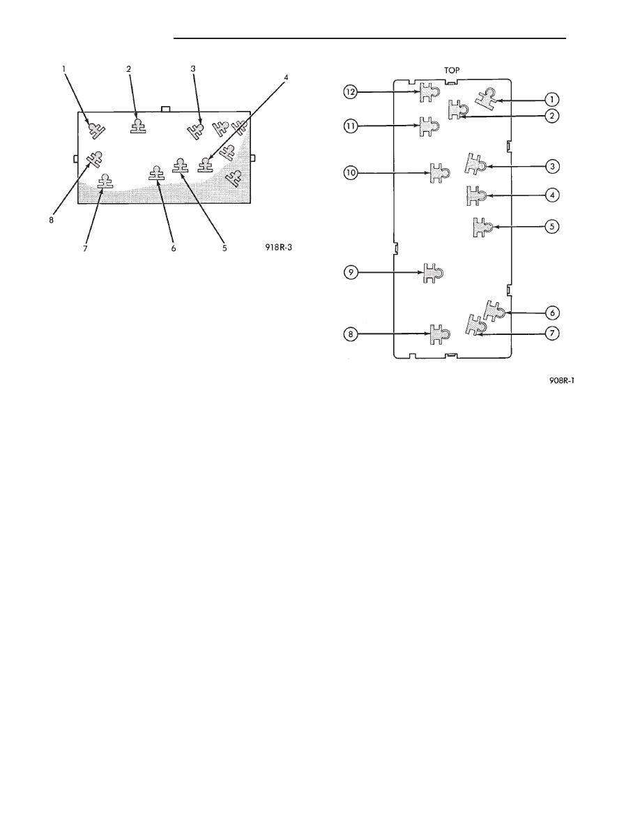
AG & AJ BODIES
(1) Remove switch from mounting position and dis-
connect from harness.
(2) To check the front motor, connect a jumper
wire between cavity number 2 and cavity number 9
(Fig. 2). Connect a second jumper wire between cav-
ity number 6 and cavity number 5. If the motor does
not operate, reverse the jumpers, 2 to 5 and 6 to 9. If
motor still does not operate check wiring between
switch connector and motor assembly. If wiring
checks good replace motor assembly.
(3) To check the center motor, connect a jumper
wire between cavity number 2 and cavity number 8.
Connect a second jumper wire between cavity 6 and
cavity number 7. If the motor does not operate, re-
verse the jumpers, 2 to 7 and 6 to 8. If motor still
does not operate check wiring between switch con-
nector and motor assembly. If wiring checks good re-
place motor assembly.
(4) To check the rear motor, connect a jumper be-
tween cavity number 2 and cavity number 10. Con-
nect a second jumper wire between cavity number 6
and cavity number 3. If the motor does not operate,
reverse the jumpers, 2 to 3 and 6 to 10. If motor still
does not operate, check wiring between switch con-
nector and motor assembly. If wiring checks good re-
place motor assembly.
(5) To check the seat back recliner motor if
equipped, connect a jumper wire be tween cavity
number 2 and cavity number 1. Connect a second
jumper wire between cavity number 6 and cavity
number 11. If the motor does not operate, reverse the
jumpers (2 to 11 and 6 to 1). If motor still does not
operate check wiring be tween switch connector and
motor assembly. If wiring checks good replace motor
assembly.
(6) If all motors and the seat operate properly, per-
form Switch Test.
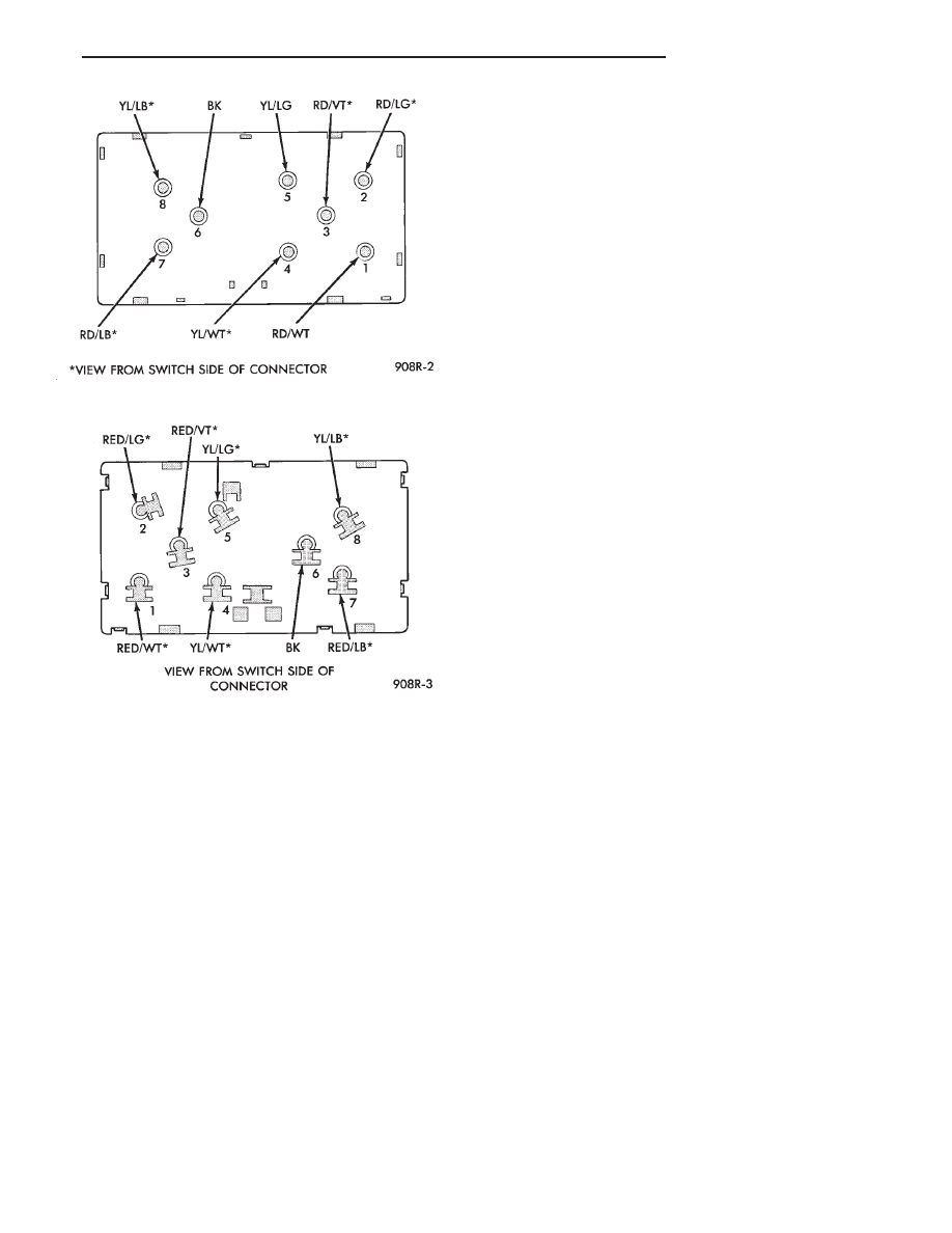
AC AND AY BODIES
The following tests do not apply to left seat on ve-
hicles equipped with memory mirrors/seats. Refer to
test procedures for power memory mirrors/seats in
this section.
(1) Remove switch from mounting position and dis-
connect from harness.
(2) To check the front motor, connect a jumper
wire between cavity number 3 and cavity number 8
(Fig. 3 and 4). Connect a second jumper wire between
cavity number 6 and cavity number 7. If the motor
does not operate, reverse the jumpers, 3 to 7 and 6 to
8. If the motor still does not operate check the wiring
between switch connector and motor assembly. If
wiring checks good replace motor assembly.
(3) To check the center motor, connect a jumper
wire between cavity number 3 and cavity number 5.
Connect a second jumper wire between cavity num-
ber 6 and cavity number 2. If the motor does not op-
erate, reverse the jumpers, 3 to 2 and 6 to 5. If the
motor still does not operate check the wiring between
Fig. 1 Power Seat Switch Connector—AA Body
Fig. 2 Power Seat Switch Connector—AG & AJ
Bodies
8R - 2
POWER SEATS
Ä
switch connector and motor assembly. If wiring
checks good replace motor assembly.
(4) To check the rear motor, connect a jumper wire
between cavity number 3 and cavity number 4. Con-
nect a second jumper wire between cavity number 6
and cavity number 13. If the motor does not operate,
reverse the jumpers, 3 to 13 and 6 to 4. If the motor
still does not operate check the wiring between
switch connector and motor assembly. If wiring
checks good replace motor assembly.
(5) If all motors and the seat operate properly, per-
form Switch Test.
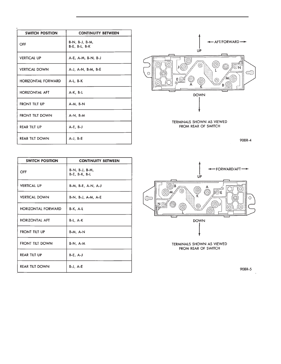
SWITCH TEST
To check the switch, remove the switch from its
mounting position. Using an ohmmeter, perform
switch continuity test (Fig. 5, 6 and 7). If there is no
continuity at any one of the switch positions, replace
the switch.
SEAT ASSEMBLY
REMOVAL
(1) Remove plastic covers.
(2) Remove adjuster attaching bolts and nuts from
floor pan. Move adjuster as required for access.
(3) Disconnect battery negative cable.
(4) Disconnect wiring harness power lead at car-
pet.
(5) Remove seat assembly from vehicle.
INSTALLATION
(1) Position seat assembly in vehicle.
(2) Connect wiring harness.
(3) Install and tighten mounting bolts and nuts to
28 N
Im (250 in. lbs.) torque.
(4) Connect battery negative cable and check seat
operation.
(5) Install plastic covers.
HORIZONTAL AND VERTICAL TRANSMISSIONS
Transmissions are not removable and no mainte-
nance is required. If transmission fails replace entire
seat adjuster assembly.
ADJUSTER
REMOVAL
(1) Remove seat assembly from vehicle following
procedure outlined under Seat Assembly Removal.
(2) Lay seat on its back on some clean surface.
(3) Remove bolts attaching adjuster to seat assem-
bly (Fig. 8 Through 11).
(4) Disconnect wiring harness at switch if seat
mounted switch is used.
(5) Remove tie straps holding cable housing to seat
for power bench seat adjuster only.
INSTALLATION
(1) Lay seat on its back on a clean surface.
(2) Position adjuster to seat assembly and install
attaching bolts.
(3) Connect wiring harness at switch and replace
tie straps where removed.
(4) Install seat following procedure outlined under
Seat Assembly Installation.
MOTOR
REMOVAL
Anytime the motor, cable and housing assemblies,
or vertical and horizontal transmission assemblies,
require maintenance, the assemblies must be syn-
chronized to insure easy and proper operation.
(1) Remove seat assembly from vehicle following
procedure outlined under Seat Assembly Removal
(Fig. 8 through 11).
(2) Lay seat assembly on its back on a clean sur-
face.
Fig. 3 Left Power Seat Switch—AC & AY Bodies
Fig. 4 Right Power Seat Switch—AC & AY Bodies
Ä
POWER SEATS
8R - 3
(3) Remove motor mounting screws.
(4) Carefully disconnect housing and cables from
motor assembly.
INSTALLATION
(1) Place motor assembly into position.
(2) Carefully connect cables and housings to motor
assembly.
(3) Install mounting screws.
(4) Install bolt holding motor assembly to adjuster.
(5) Install seat following procedure outlined under
Seat Assembly Installation.
ENTHUSIAST SEAT
AG and AJ body vehicles have, as an option, a spe-
cial enthusiast seat package. The seat includes not
only the normal six-way power seat adjuster, but also
special lumbar air filled support bag and adjustable
seat back side wings (Fig. 12). These mechanisms are
adjusted by a switch located on the right side seat
Fig. 5 Switch Continuity—AA Body
Fig. 6 Switch Continuity—AJ Body
8R - 4
POWER SEATS
Ä
Нет комментариевНе стесняйтесь поделиться с нами вашим ценным мнением.
Текст