Chrysler Le Baron, Dodge Dynasty, Plymouth Acclaim. Manual — part 77
FRONT SUSPENSION SERVICE PROCEDURES
INDEX
page
page
Ball Joints
. . . . . . . . . . . . . . . . . . . . . . . . . . . . . . 13
Hub and Bearing Assembly
. . . . . . . . . . . . . . . . . 20
Knuckle (Front Suspension)
. . . . . . . . . . . . . . . . . 16
Lower Control Arm
. . . . . . . . . . . . . . . . . . . . . . . 10
Lower Control Arm Pivot Bushings
. . . . . . . . . . . 11
Shock Absorbers (Strut Damper)
. . . . . . . . . . . . . 10
Strut Damper Assembly
. . . . . . . . . . . . . . . . . . . . . 7
Suspension Coil Springs
. . . . . . . . . . . . . . . . . . . . 9
Sway Bar
. . . . . . . . . . . . . . . . . . . . . . . . . . . . . . 14
Wheel Alignment
. . . . . . . . . . . . . . . . . . . . . . . . . . 5
WHEEL ALIGNMENT
Front wheel alignment is the proper adjustment of
all interrelated front suspension angles. These angles
are what affects the running and steering of the
front wheels of the vehicle.
The method of checking front alignment will vary
depending on the type of equipment being used. The
instructions furnished by the manufacturer of the
equipment should always be followed. With the ex-
ception that the alignment specifications recom-
mended by Chrysler Corporation be used.
There are six basic factors which are the founda-
tion to front wheel alignment. These are height,
caster, camber, toe-in, steering axis inclination and
toe-out on turns. Of the six basic factors only camber
and toe in are mechanically adjustable (Fig. 1)
CAUTION: Do not attempt to modify any suspen-
sion or steering components by heating or bending
of the component.
Wheel alignment adjustments and checks should be
made in the following sequence.
(1) Camber
(2) Toe
Camber is the number of degrees the top of the
wheel is tilted inward or outward from true vertical.
Inward tilt is negative camber. Outward tilt is posi-
tive camber.
Excessive camber is a tire wear factor: negative
camber causes wear on the inside of the tire, while
positive camber causes wear to the outside.
Toe is measured in degrees or inches and is the
distance the front edges of the tires are closer (or far-
ther apart) than the rear edges. See Front Wheel
Drive Specifications for Toe settings.
PRE-ALIGNMENT
Before any attempt is made to change or correct
the wheel alignment factors. The following inspection
and necessary corrections must be made on those
parts which influence the steering of the vehicle.
(1) Check and inflate tires to recommended pres-
sure. All tires should be the same size and in good
condition and have approximately the same wear.
Note type of tread wear which will aid in diagnosing,
see Wheels and Tires, Group 22.
(2) Check front wheel and tire assembly for radial
runout.
(3) Inspect lower ball joints and all steering link-
age for looseness.
(4) Check for broken or sagged front and rear
springs.
Front suspension must only be checked after the
vehicle has had the following checked or adjusted.
Tires set to recommended pressures, full tank of fuel,
no passenger or luggage compartment load and is on
a level floor or alignment rack.
Just prior to each alignment reading. The vehicle
should be bounced (rear first, then front) by grasping
bumper at center and jouncing each end an equal
number of times. Always release bumpers at bottom
of down cycle.
Ä
SUSPENSION AND DRIVESHAFTS
2 - 5
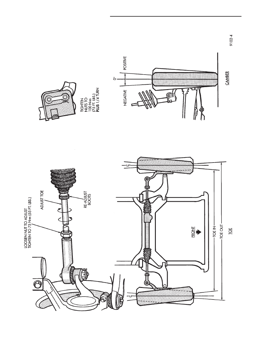
Fig.
1
Alignment
Camber/T
oe
2 - 6
SUSPENSION AND DRIVESHAFTS
Ä
WHEEL ALIGNMENT SERVICE PROCEDURE
CAMBER AA, AJ BODIES
(1) Prepare vehicle as described in the Pre-Align-
ment procedure.
(2) Loosen cam and knuckle bolts (each side) (Fig.
2).
(3) Rotate cam bolt (Fig. 2) to move top of wheel in
or out to specified camber.
(4) Tighten the cam bolts and nuts to 100 N
Im (75
ft. lbs.) plus 1/4 turn beyond specified torque.
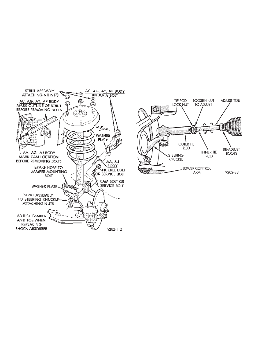
CAMBER AC, AG, AP, AY BODIES
(1) Prepare vehicle as described in the Pre-Align-
ment procedure.
(2) Position vehicle on alignment equipment and
read camber as instructed by equipment manufactur-
er’s procedure.
(3) Using extensions and appropriate tools. Re-
move the strut assembly to steering knuckle attach-
ing bolts from vehicle (Fig. 2). Replace the original
attaching bolts with the bolts provided in the align-
ment, Cam And Bolt Service Package.
(4) Rotate the alignment adjusting cam bolt, (Fig.
2) to obtain the specified camber setting for the ve-
hicle. See the Specifications Section at the end of this
group for the camber setting for the vehicle being
serviced.
(5) Using the appropriate extensions and tools.
Carefully reach around the tire and tighten the
knuckle bolts enough to hold the camber setting.
Finish by tightening the bolts to 100 N
Im (75 ft.lbs.)
plus 1/4 turn beyond specified torque.
TOE
(1) Prepare vehicle as described in the Pre-Align-
ment procedure.
(2) Center steering wheel and hold with steering
wheel clamp.
(3) Loosen tie rod locknuts. Rotate rods to align toe
to specifications (Fig. 3).
CAUTION: Do not twist tie rod to steering gear rub-
ber boots during adjustment.
(4) Tighten tie rod locknuts to 75 N
Im (55 ft.lbs.)
torque.
(5) Adjust steering gear to tie rod boots at tie rod.
(6) Remove steering wheel clamp.
STRUT DAMPER ASSEMBLY
REMOVAL
(1) Loosen wheel nuts.
(2) Raise vehicle, see Hoisting in Lubrication and
Maintenance, Group 0.
(3) Remove wheel and tire assembly.
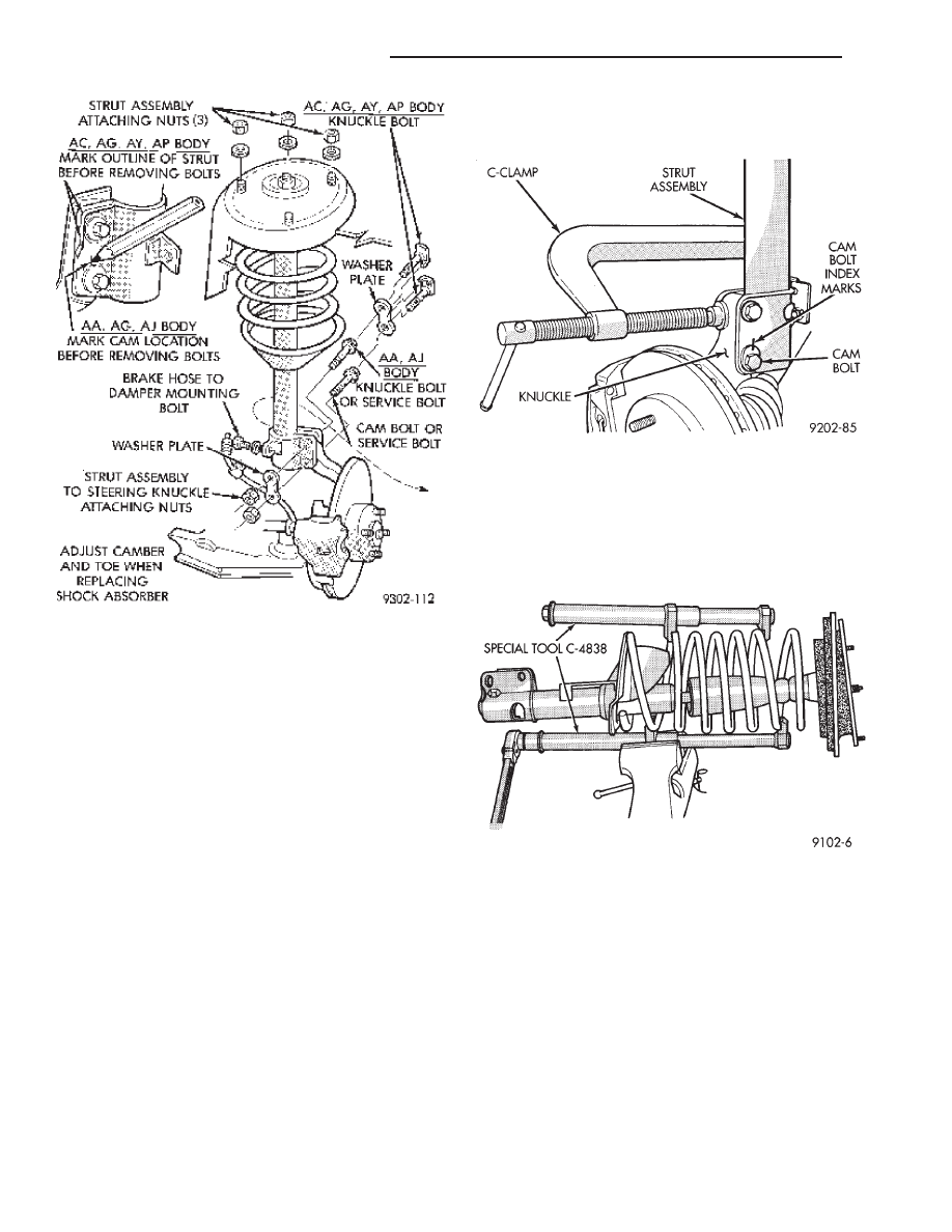
Where service procedure includes assembly of
original
strut
(shock
absorber)
to
original
knuckle. Mark cam adjusting bolt (Fig. 4), on
AA, and AJ bodies only. Mark outline of strut
on knuckle as shown in (Fig. 1). on AC, AG, AP
and AY bodies.
(4) Remove cam bolt, knuckle bolt(s), washer
plate(s) and brake hose to damper bracket retaining
screw (Fig. 4).
(5) Remove strut damper to fender shield mount-
ing nut washer assemblies.
Fig. 2 Alignment Adjustment Locations
Fig. 3 Front Wheel Toe Adjustment
Ä
SUSPENSION AND DRIVESHAFTS
2 - 7
INSPECTION
Inspect for evidence of fluid running from the up-
per end of the reservoir. (Actual leakage will be a
stream of fluid running down the side and dripping
off lower end of unit). A slight amount of seepage be-
tween the strut rod and strut shaft seal is not un-
usual and does not affect performance of the strut
assembly.
INSTALLATION
(1) Install unit into fender reinforcement and in-
stall retaining nuts and washer assemblies (Fig. 1).
Tighten the 3 nuts to 27 N
Im (20 ft. lbs.) torque.
(2) Position steering knuckle neck into strut as-
sembly. Position washer plate and install cam and
knuckle bolts (Fig. 4).
(3) Attach brake hose retainer to damper, tighten
the screw to 13 N
Im (10 ft. lbs.) torque (Fig. 4).
(4) Index strut to original outline on the knuckle
neck, or align mark on cam bolt with the mark that
was put on the strut to steering knuckle bracket
(Fig. 4).
(5) Place a 4 inch (or larger) C clamp on the strut
and knuckle as shown in (Fig. 5). Tighten the clamp
just enough to eliminate any looseness between the
knuckle and the strut. Check alignment of the index
marks and tighten the bolts to 100 N
Im (75 ft. lbs.)
plus 1/4 turn beyond specified torque. Remove the
(C) clamp.
(6) Install wheel and tire assembly. Tighten the
wheel nuts to 129 N
Im (95 ft. lbs.) torque.
DISASSEMBLY (STRUT DAMPER)
(1) Compress front coil spring with Spring Com-
pressor, Special Tool C-4838 (Fig. 6).
(2) Hold end of strut shaft from rotating with
wrench, while loosening strut shaft nut. Remove nut
from shaft (Fig. 7).
(3) Remove the upper strut mount from the strut
assembly.
(4) Remove coil spring from the strut assembly.
Mark spring for installation back on the same
side of the vehicle (Fig. 11).
CAUTION: see Suspension Coil Springs before re-
leasing coil from Tool C-4838.
(5) Inspect strut damper, mount assembly (Fig. 8)
for:
Fig. 4 Strut Damper Removal
Fig. 5 Strut Damper Installation
Fig. 6 Compressing Coil Spring
2 - 8
SUSPENSION AND DRIVESHAFTS
Ä
Нет комментариевНе стесняйтесь поделиться с нами вашим ценным мнением.
Текст