Chrysler Le Baron, Dodge Dynasty, Plymouth Acclaim. Manual — part 570

(6) Remove Bracket bolts #2 and #3 from rear of
engine. Remove Bracket (Fig. 13).
INSTALLATION
(1) Loose assemble bracket to engine.
(2) Tighten bolts #2 and #3 to 3.3 N
Im (30 in. lbs.)
(Fig. 13).
(3) Tighten timing belt idler pulley and tighten to
54 N
Im (40 ft. lbs.) (Fig. 12).
(4) Tighten bolts 32 and #3 to 54 N
Im (40 ft. lbs.)
(Fig. 13).
(5) Camshaft and Crankshaft timing should be
checked at this time.
Adjust as necessary following procedure outlined in
this section.
(6) Install power steering pump on bracket tighten
bolts to 28 N
Im (250 in. lbs.) torque (Fig. 11).
(7) Install timing belt covers. Refer to procedure
outlined in this section.
CAUTION: Do not use impact wrench on accessory
drive belt tensioner bolt. It may cause damage to
tensioner arm.
(8) Install accessory drive belt tensioner pulley
bolt finger tight. Then tighten bolt to 54 N
Im (40 ft.
lbs.) torque. Install accessory drive belt, Refer to
Cooling System Group 7 for procedure.
Fig. 11 Power Steering Pump Attaching Bolts
Fig. 12 Power Steering Pump Bracket and Timing
Belt Idler Bolt
Fig. 13 Power Steering Pump/Accessory Drive Belt
Tensioner Bracket Attaching Bolts
Ä
2.2/2.5L ENGINE
9 - 17
TIMING SYSTEM AND SEALS SERVICE—EXCEPT TURBO III
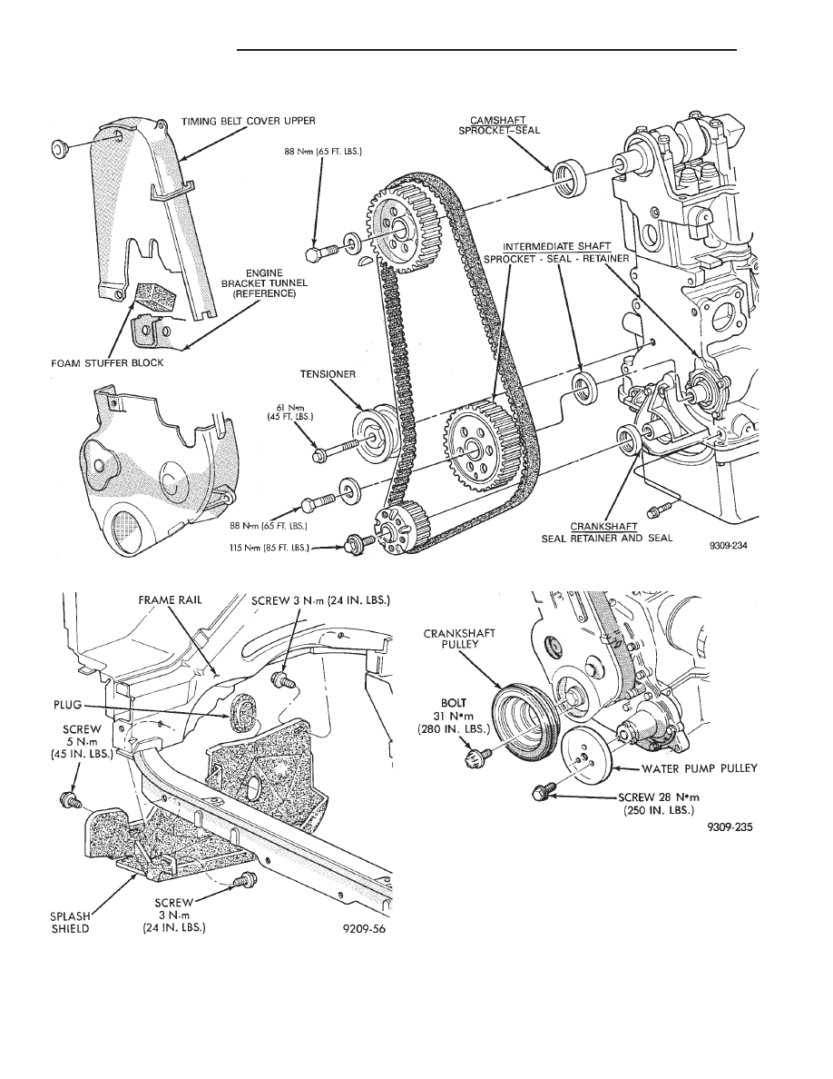
Refer to (Fig. 1) for parts identification and torque
specifications
TIMING BELT SERVICE
(1) Remove Solid Mount Compressor Bracket. Re-
fer to procedure outlined in this section.
(2) Raise vehicle on a hoist and remove right inner
splash shield (Fig. 2).
(3) Remove screws retaining water pump pulley
and bolts retaining crankshaft pulley (Fig. 3) and lay
pullies aside.
(4) Remove nuts holding cover to cylinder head.
Fig. 2 Right Inner Splash Shield
Fig. 3 Crankshaft and Water Pump Pulley
Fig. 1 Timing System and Seals
9 - 18
2.2/2.5L ENGINE
Ä
(5) Remove screws holding cover to cylinder block.
(6) Remove both halves of timing belt cover and
lay aside (Fig. 4)
(7) Place a jack under engine.
(8) Separate right engine mount (Fig. 5) and raise
engine slightly.
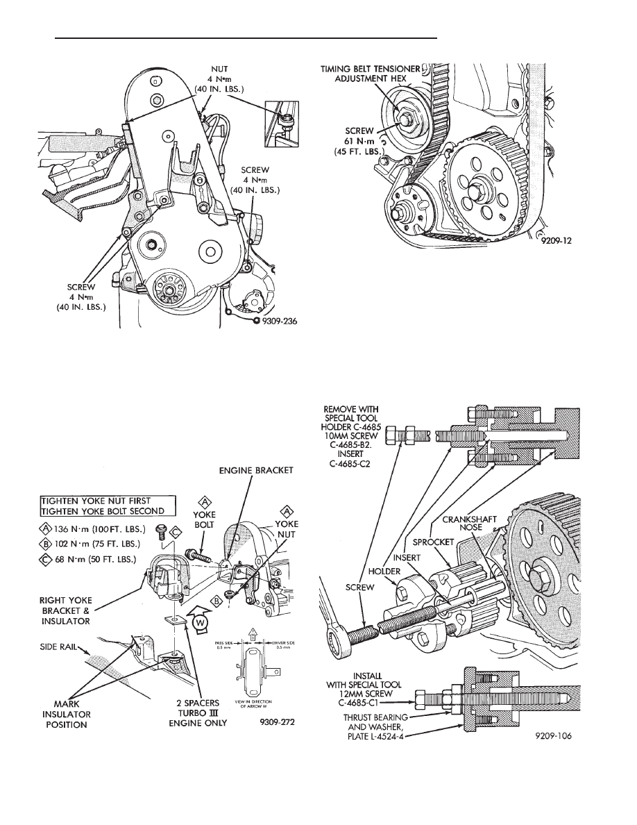
(9) Loosen timing belt tensioner screw (Fig. 6) and
remove timing belt.
SERVICING FRONT OIL
SEALS—REPLACEMENT
(1) With timing belt removed, remove crankshaft
sprocket bolt.
(2) Remove crankshaft sprocket using Special Tool
C-4685, Insert and 5.9 inch long screw (Fig. 7).
(3) Install crankshaft sprocket using plate L-4524,
Thrust Bearing/washer and 5.9 inch long screw (Fig.
7).
Fig. 4 Timing Belt Cover
Fig. 7 Crankshaft Sprocket
Fig. 5 Right Engine Mount
Fig. 6 Remove Timing Belt
Ä
2.2/2.5L ENGINE
9 - 19

(4) Hold engine sprocket with Special Tool C-4687
(with adaptor Tool C-4687-1) while removing/install-
ing screw (Fig. 8). The 2.5L Engine camshaft/inter-
mediate shaft sprockets have an off-set hub and are
identified with a six-hole pattern .
(5) Remove crankshaft seal using Special Tool
6341. Remove intermediate and camshaft seals using
Special Tool C-4679 (Fig. 10).
CAUTION: Do not nick shaft seal surface or seal
bore.
(6) Shaft seal lip surface must be free of varnish,
dirt or nicks. Polish with 400 grit paper if necessary.
(7) Install engine crankshaft seal into retainer us-
ing Special Tool 6342 and 6343. Install Intermediate
and Camshaft seals using Special Tool C-4680. In-
stall seals until flush (Fig. 10).
CAMSHAFT, CRANKSHAFT AND INTERMEDIATE
SHAFTS TIMING PROCEDURE
(1) Remove all spark plugs. Turn crankshaft and
intermediate shaft until markings on sprockets are
in line, see arrows (Fig. 11 ).
Fig. 9 Removing Crankshaft, Intermediate Shaft and
Camshaft Oil Seal
Fig. 8 Removing/Installing Camshaft or Intermediate
Shaft Sprocket Screw
Fig. 10 Installing Crankshaft,Intermediate Shaft, and
Camshaft Seal
Fig. 11 Crankshaft and Intermediate Shaft Timing
9 - 20
2.2/2.5L ENGINE
Ä
Нет комментариевНе стесняйтесь поделиться с нами вашим ценным мнением.
Текст