Chrysler Le Baron, Dodge Dynasty, Plymouth Acclaim. Manual — part 590
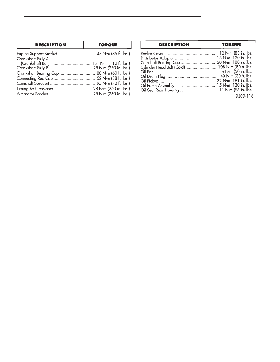
TORQUE
Ä
3.0L ENGINE
9 - 97
3.3/3.8L ENGINE
INDEX
page
page
Camshaft
. . . . . . . . . . . . . . . . . . . . . . . . . . . . . . 112
Camshaft Bearings—Engine Removed From
Vehicle
. . . . . . . . . . . . . . . . . . . . . . . . . . . . . . 113
Checking Engine Oil Pressure
. . . . . . . . . . . . . . 125
Connecting Rods
. . . . . . . . . . . . . . . . . . . . . . . . 118
Crankshaft Oil Seals Service
. . . . . . . . . . . . . . . 121
Crankshaft Service
. . . . . . . . . . . . . . . . . . . . . . 118
Cylinder Block, Piston and Connecting Rod
Assembly Service
. . . . . . . . . . . . . . . . . . . . . . 114
Cylinder Heads
. . . . . . . . . . . . . . . . . . . . . . . . . 102
Engine Assembly
. . . . . . . . . . . . . . . . . . . . . . . . 101
Engine Core Oil and Cam Plugs
. . . . . . . . . . . . 113
Engine Lubrication System
. . . . . . . . . . . . . . . . 122
Engine Mounts
. . . . . . . . . . . . . . . . . . . . . . . . . . 99
Engine Specifications
. . . . . . . . . . . . . . . . . . . . . 126
General Information
. . . . . . . . . . . . . . . . . . . . . . . 98
Hydraulic Tappets
. . . . . . . . . . . . . . . . . . . . . . . 108
Installing Piston and Connecting Rod Assembly
. 117
Intake Manifold Sealing
. . . . . . . . . . . . . . . . . . . 104
Oil Filter
. . . . . . . . . . . . . . . . . . . . . . . . . . . . . . 125
Oil Pan Service
. . . . . . . . . . . . . . . . . . . . . . . . . 122
Oil Pump Service
. . . . . . . . . . . . . . . . . . . . . . . 123
Rocker Arms and Shaft Assembly
. . . . . . . . . . . 102
Timing Chain Cover, Oil Seal and Chain
. . . . . . 109
Valve Service
. . . . . . . . . . . . . . . . . . . . . . . . . . 104
Valve Timing
. . . . . . . . . . . . . . . . . . . . . . . . . . . 109
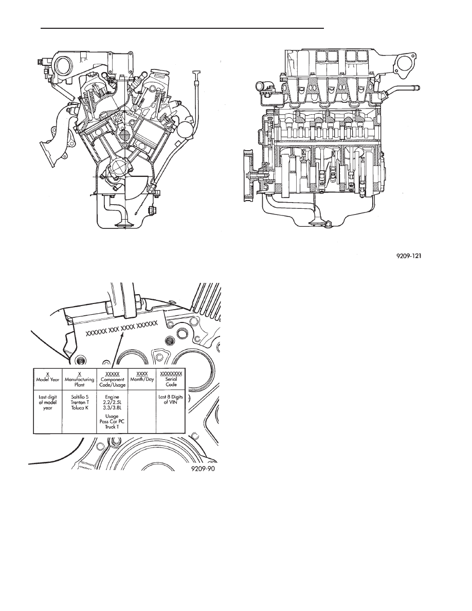
GENERAL INFORMATION
ENGINE IDENTIFICATION NUMBER OR CODE
The engine identification number is located on the
rear of the cylinder block just below the cylinder
head (Fig. 2).
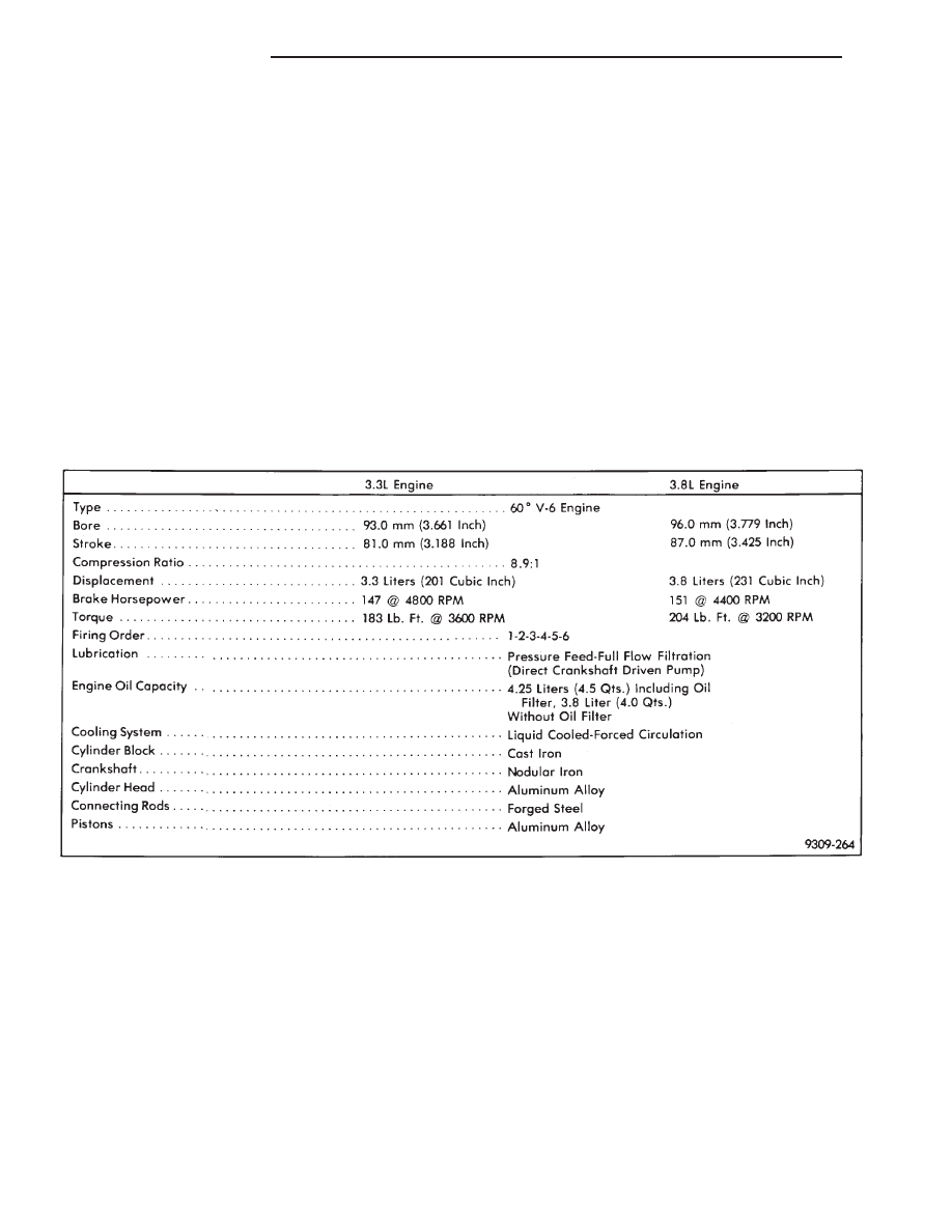
ENGINE: The 3.3L (201 Cubic. Inches.) and 3.8L
(231 Cubic. Inches.) displacement engines are 60° V
type six cylinder power plant with cast iron cylinder
block and aluminum cylinder heads (Fig. 1). Firing
order for these engines is 1-2-3-4-5-6. High turbu-
lence cylinder heads allow a 8.9-1 compression ratio.
CRANKSHAFT: The nodular iron crankshaft is
supported by four main bearings, with number two
being the thrust bearing. Crankshaft end sealing is
provided by front and rear rubber seal.
PISTONS: The pistons are cast aluminum alloy.
Three rings are used. Piston pins, press fitted into
place, join the pistons to forged steel connecting rods.
CAMSHAFT:
The
nodular
iron
camshaft
is
mounted in four steel backed babbitt bearings. A
thrust plate located in front of the first bearing, and
bolted to the block, controls end play. Silent timing
chain drives the camshaft. This chain is enclosed by
a cast aluminum cover which also carries a front
crankshaft seal, provides front oil pan closure, water
pump mounting.
SPECIFICATIONS
9 - 98
3.3/3.8L ENGINE
Ä
CYLINDER HEADS: Cylinder heads incorporate
valve shrouding to create turbulence-producing com-
bustion chambers, described as fast burn. Valve seat
and guides are inserts. A steel flanged composition
type gasket is used between head and block.
VALVE COVERS: The covers are sealed with
steel reinforced silicon rubber gaskets.
INTAKE MANIFOLD: The intake manifold is a
tuned two-piece semi-permanent mold aluminum
casting with individual primary runners leading
from a plenum to the cylinders. The manifold is de-
signed to boost torque in the 3600 rpm range and
contributes to the engine’s broad, flat torque curve,
which was desired for excellent engine tractability,
response and usable power output.
The intake manifold is also cored with upper level
EGR passages for balanced cylinder to cylinder EGR
distribution.
VALVE TRAIN: Valve train design incorporates
the use of hydraulic roller tappets. Rocker arms are
installed on a rocker arm shaft attached to the cylin-
der head with four bolts and retainers. Viton valve
stem seals provide valve sealing. Conventional type
pushrods, retainers and valve stem locks are used.
Unique beehive style valve spring are used with
lightweight retainers for improved high RPM perfor-
mance.
EXHAUST MANIFOLDS: Exhaust manifolds are
log type with a crossover and is attached directly to
the cylinder heads.
ENGINE MOUNTS
REMOVAL AND INSTALLATION
RIGHT SIDE MOUNT
(1) Remove the right engine mount insulator ver-
tical fasteners from frame rail.
(2) Remove the load on the engine motor mounts
by carefully supporting the engine and transmission
assembly with a floor jack.
Fig. 1 3.3/3.8L V-6 Engine
Fig. 2 Engine Identification
Ä
3.3/3.8L ENGINE
9 - 99
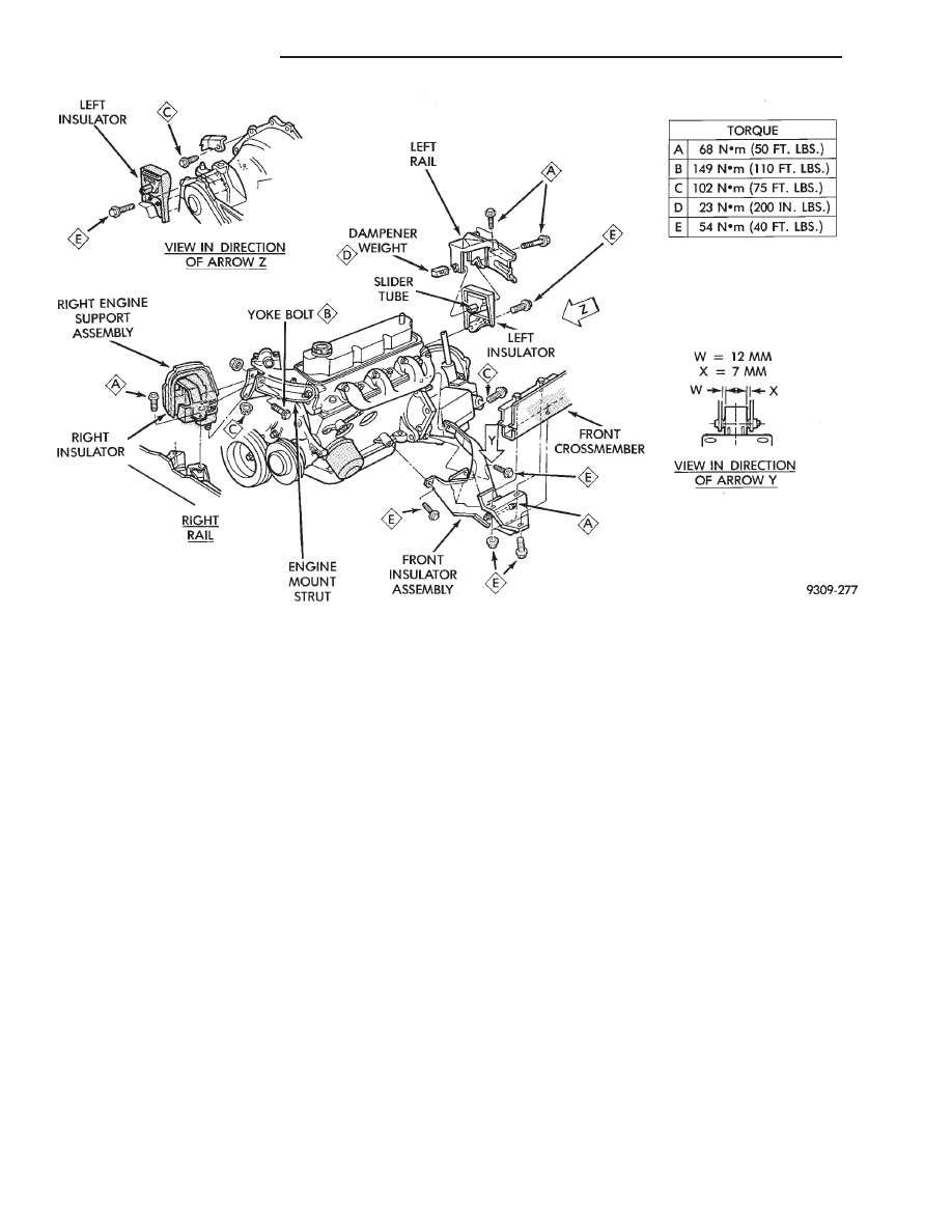
(3) Remove the thru bolt from the insulator assem-
bly. Remove insulator.
(4) Reverse removal procedure for installation. Re-
fer to (Fig. 3) for bolt tightening specifications.
(5) Engine mount adjustment, Refer to Engine
Mount Insulator Adjustment of this section.
FRONT MOUNT
(1) Support the engine and transmission assembly
with a floor jack so it will not rotate.
(2) Remove the thru bolt from the insulator and
front crossmember mounting bracket.
(3) Remove the front engine mount bracket to
front crossmember screws and nuts. Remove the in-
sulator assembly.
(4) Reverse removal procedure for installation. Re-
fer to (Fig. 3) for bolt tightening specifications.
(5) Engine mount adjustment, Refer to Engine
Mount Insulator Adjustment of this section.
LEFT SIDE MOUNT
(1) Raise vehicle on hoist and remove left front
wheel.
(2) Remove inter splash shield.
(3) Support the transmission with a transmission
jack.
(4) Remove the insulator thru bolt from the mount.
(5) Remove the transmission mount fasteners and
remove mount.
(6) Reverse removal procedure for installation. En-
sure that the slide tube is seated into the rail
bracket guides. Refer to (Fig. 3) for bolt tightening
specifications.
(7) Engine mount adjustment, Refer to Engine
Mount Insulator Adjustment of this section.
ENGINE MOUNT RUBBER INSULATORS
Insulator location on yoke bracket to engine plate
(right side) and transmission bracket (left side) are
adjustable to allow right/left drive train adjustment
in relation to drive shaft assembly length.
Check and reposition right engine mount insulator
(left engine mount insulator is floating type and will
adjust automatically (Fig. 4). Adjust drive train posi-
tion, if required, for the following conditions:
• Drive shaft distress: See Driveshafts in Suspen-
sion, Group 2.
• Any front end structural damage (after repair).
• Insulator replacement.
ENGINE MOUNT INSULATOR ADJUSTMENT
(1) Remove the load on the engine motor mounts
by carefully supporting the engine and transmission
assembly with a floor jack.
Fig. 3 Engine Mounting
9 - 100
3.3/3.8L ENGINE
Ä
Нет комментариевНе стесняйтесь поделиться с нами вашим ценным мнением.
Текст