Chrysler Le Baron, Dodge Dynasty, Plymouth Acclaim. Manual — part 122
FLUID LEVEL AND CONDITION
The transmission and differential sump have a
common oil sump with a communicating opening
between the two.
The torque converter fills in both the P Park and N
Neutral positions. Place the selector lever in P Park to
check the fluid level. The engine should be running
at idle speed for at least one minute, with the
vehicle on level ground. This will assure com-
plete oil level stabilization between differential
and transmission. The fluid should be at normal
operating temperature (approximately 82 C. or 180 F.).
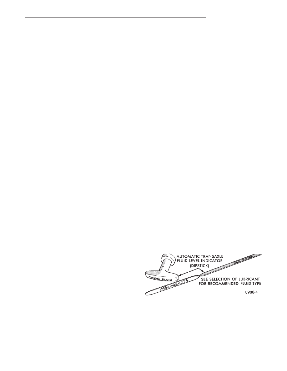
The fluid level is correct if it is in the HOT region
(cross-hatched area) on the oil level indicator.
Low fluid level can cause a variety of conditions
because it allows the pump to take in air along with the
fluid. As in any hydraulic system, air bubbles make the
fluid spongy, therefore, pressures will be low and build
up slowly.
Improper filling can also raise the fluid level too
high. When the transaxle has too much fluid, the gears
churn up foam and cause the same conditions which
occur with a low fluid level.
In either case, the air bubbles can cause over heat-
ing, fluid oxidation, and varnishing, which can inter-
fere with normal valve, clutch, and accumulator opera-
tion. Foaming can also result in fluid escaping from the
transaxle vent where it may be mistaken for a leak.
Along with fluid level, it is important to check the
condition of the fluid. When the fluid smells burned,
and is contaminated with metal or friction material
particles, a complete transaxle overhaul is needed. Be
sure to examine the fluid on the dipstick closely. If
there is any doubt about its condition, drain out a
sample for a double check.
After the fluid has been checked, seat the dipstick
fully to seal out water and dirt.
SELECTION OF LUBRICANT
It is important that the proper lubricant be used in
the 41TE transaxle. MOPAR
t ATF PLUS (Automatic
Transmission Fluid—type 7176) should be used to aid
in assuring optimum transmission performance. Flu-
ids of the type labeled DEXRON II Automatic Trans-
mission Fluid are not recommended. DEXRON II
can be used only if the recommended fluid is not
available. If more than a small amount of DEXRON II
is used shudder or shift quality problems may result. It
is important that the transmission fluid be maintained
at the prescribed level using the recommended fluids.
SPECIAL ADDITIVES
Chrysler Corporation does not recommend the addi-
tion of any fluids to the transaxle, other than the
automatic transmission fluid listed above. An excep-
tion to this policy is the use of special dyes to aid in
detecting fluid leaks. The use of transmission sealers
should be avoided, since they may adversely affect
seals.
FLUID AND FILTER CHANGES
When the factory fill fluid is changed, only fluids
labeled MOPAR
t ATF PLUS (Automatic Transmis-
sion fluid) Type 7176 should be used. A filter change
should be made at the time of the oil change. Also
the magnet (on the inside of the oil pan) should be
cleaned with a clean, dry cloth.
If the transaxle is disassembled for any reason, the
fluid and filter should be changed.
FLUID DRAIN AND REFILL
(1) Raise vehicle on a hoist (See Lubrication,
Group 0). Place a drain container with a large open-
ing, under transaxle oil pan.
(2) Loosen pan bolts and tap the pan at one corner
to break it loose allowing fluid to drain, then remove
the oil pan.
(3) Install a new filter and O-ring on bottom of the
valve body.
(4) Clean the oil pan and magnet. Reinstall pan
using new MOPAR
t Adhesive Sealant. Tighten oil
pan bolts to 19 N
Im (165 in. lbs.).
(5) Pour four quarts of MOPAR
t ATF PLUS (Au-
tomatic Transmission Fluid) Type 7176 through the
fill tube.
(6) Start engine and allow to idle for at least one
minute. Then, with parking and service brakes ap-
plied, move selector lever momentarily to each posi-
tion, ending in the park or neutral position.
(7) Add sufficient fluid to bring level to 1/8 inch
below the ADD mark.
Recheck fluid level after transaxle is at normal op-
erating temperature. The level should be in the HOT
region (Fig. 3).
To prevent dirt from entering transaxle, make cer-
tain that dipstick is seated into the dipstick fill tube
(Fig. 4).
ROAD TEST
Prior to performing a road test, be certain that the
fluid level and condition, and control cable adjust-
ment have been checked and approved.
Fig. 3 Oil Level Indicator
Ä
TRANSAXLE
21 - 93
During the road test, the transaxle should be oper-
ated in each position to check for slipping and any
variation in shifting.
If vehicle operates properly at highway speeds, but
has poor acceleration, the torque converter stator
overrunning clutch may be slipping. If through-gear
acceleration is normal, but high throttle opening is
required to maintain highway speeds, the torque con-
verter stator clutch may have seized. Both of these
stator defects require replacement of the torque con-
verter.
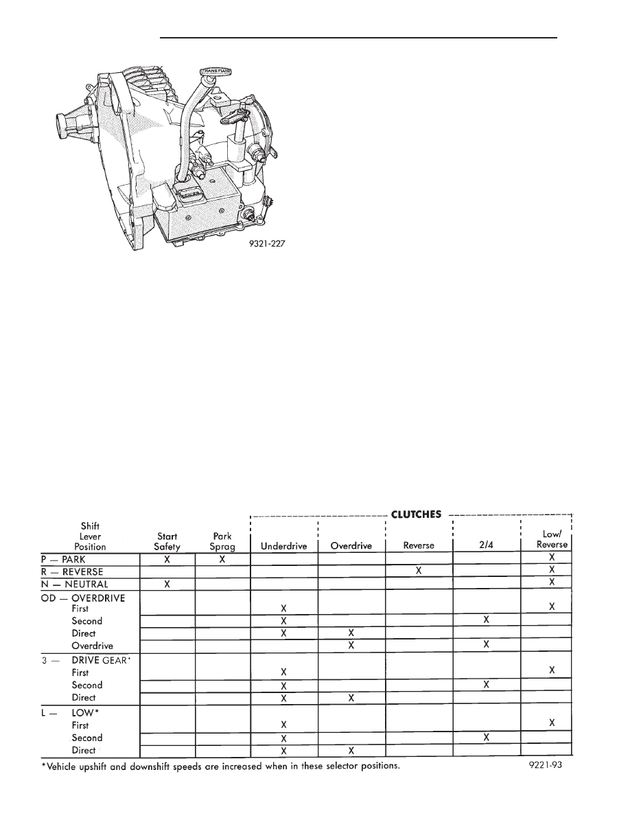
The clutch that is slipping can be determined by
noting the transaxle operation in all selector posi-
tions. Then comparing which internal units are ap-
plied in those positions. The Elements in Use Chart
provides a basis for road test analysis.
The process of elimination can be used to detect
any unit which slips and to confirm proper operation
of good units. Road test analysis can usually diag-
nose slipping units, but the actual cause of the mal-
function usually can not be decided. Practically any
condition can be caused by leaking hydraulic circuits
or sticking valves.
HYDRAULIC PRESSURE TESTS
Pressure testing is a very important step in the di-
agnostic procedure. These tests usually reveal the
cause of most transaxle problems.
Before performing pressure tests, be certain that
fluid level and condition, and shift cable adjustments
have been checked and approved. Fluid must be at
operating temperature (150 to 200 degrees F.).
Install an engine tachometer, raise vehicle on hoist
which allows front wheels to turn, and position ta-
chometer so it can be read.
Attach 150 psi gauges to ports required for test be-
ing conducted. A 300 psi gauge (C-3293) is required
for reverse pressure test.
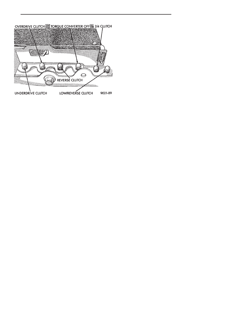
Test port locations are shown in (Figure 1).
TEST ONE-SELECTOR IN LOW 1ST GEAR
(1) Attach pressure gauge to the low/reverse clutch
tap.
(2) Move selector lever to the L position.
(3) Allow vehicle wheels to turn and increase
throttle opening to achieve an indicated vehicle
speed to 20 mph.
(4) Low/reverse clutch pressure should read 115 to
145 psi.
ELEMENTS IN USE AT EACH POSITION OF THE SELECTOR LEVER
Fig. 4 Oil Level Indicator Location
21 - 94
TRANSAXLE
Ä
(5) This test checks pump output, pressure regula-
tion and condition of the low/reverse clutch hydraulic
circuit and shift schedule.
TEST TWO-SELECTOR IN DRIVE 2ND GEAR
(1) Attach gauge to the underdrive clutch tap.
(2) Move selector lever to the 3 position.
(3) Allow vehicle wheels to turn and increase
throttle opening to achieve an indicated vehicle
speed of 30 mph.
(4) Underdrive clutch pressure should read 110 to
145 psi.
(5) This test checks the underdrive clutch hydrau-
lic circuit as well as the shift schedule.
TEST THREE-OVERDRIVE CLUTCH CHECK
(1) Attach gauge to the overdrive clutch tap.
(2) Move selector lever to the circle D position.
(3) Allow vehicle wheels to turn and increase
throttle opening to achieve an indicated vehicle
speed of 20 mph.
(4) Overdrive clutch pressure should read 74 to 95
psi.
(5) Move selector lever to the 3 position and in-
crease indicated vehicle speed to 30 mph.
(6) The vehicle should be in second gear and over-
drive clutch pressure should be less than 5 psi.
(7) This test checks the overdrive clutch hydraulic
circuit as well as the shift schedule.
TEST FOUR-SELECTOR IN CIRCLE DRIVE,
OVERDRIVE GEAR
(1) Attach gauge to the 2/4 clutch tap.
(2) Move selector lever to the circle D position.
(3) Allow vehicle front wheels to turn and increase
throttle opening to achieve an indicated vehicle
speed of 30 mph.
(4) The 2/4 clutch pressure should read 75 to 95
psi.
(5) This test checks the 2/4 clutch hydraulic circuit.
TEST FIVE-SELECTOR IN CIRCLE DRIVE,
OVERDRIVE
(1) Attach gauge to the torque converter clutch off
pressure tap.
(2) Move selector lever to the circle D position.
(3) Allow vehicle wheels to turn and increase
throttle opening to achieve an indicated vehicle speed
of 50 mph.
CAUTION: Both wheels must turn at the same speed.
(4) Torque converter clutch off pressure should be
less than 5 psi.
(5) This test checks the torque converter clutch
hydraulic circuit.
TEST SIX-SELECTOR IN REVERSE
(1) Attach gauge to the reverse clutch tap.
(2) Move selector lever to the reverse position.
(3) Read reverse clutch pressure with output sta-
tionary (foot on brake) and throttle opened to achieve
1500 rpm.
(4) Reverse clutch pressure should read 165 to 235
psi.
(5) This test checks the reverse clutch hydraulic
circuit.
TEST RESULT INDICATIONS
(1) If proper line pressure is found in any one test,
the pump and pressure regulator are working properly.
(2) Low pressure in all positions indicates a defec-
tive pump, a clogged filter, or a stuck pressure regula-
tor valve.
(3) Clutch circuit leaks are indicated if pressures do
not fall within the specified pressure range.
(4) If the overdrive clutch pressure is greater than 5
psi in step (6) of Test Three, a worn reaction shaft seal
ring is indicated.
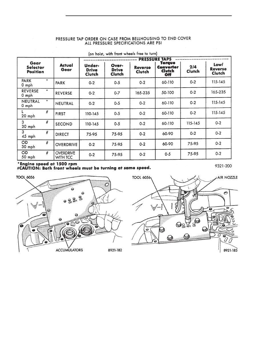
CLUTCH AIR PRESSURE TESTS
Inoperative clutches can be located using a series of
tests by substituting air pressure for fluid pressure
(Figs. 2 and 3). The clutches may be tested by applying
air pressure to their respective passages after the valve
body has been removed and Tool 6056 has been in-
stalled. To make air pressure tests, proceed as follows:
The compressed air supply must be free of all
dirt and moisture. Use a pressure of 30 psi.
Remove oil pan and valve body. See Valve body
removal.
OVERDRIVE CLUTCH
Apply air pressure to the overdrive clutch apply
passage and watch for the push/pull piston to move
Fig. 1 Pressure Taps
Ä
TRANSAXLE
21 - 95
forward. The piston should return to its starting posi-
tion when the air pressure is removed.
REVERSE CLUTCH
Apply air pressure to the reverse clutch apply pas-
sage and watch for the push/pull piston to move rear-
ward. The piston should return to its starting position
when the air pressure is removed.
2/4 CLUTCH
Apply air pressure to the feed hole located on the 2/4
clutch retainer. Look in the area where the 2/4 piston
contacts the first separator plate and watch carefully
for the 2/4 piston to move rearward. The piston should
return to its original position after the air pressure is
removed.
LOW/REVERSE CLUTCH
Apply air pressure to the low/reverse clutch feed hole
(rear of case, between 2 bolt holes). Then, look in the
area where the low/reverse piston contacts the
PRESSURE CHECK SPECIFICATIONS
Fig. 2 Air Pressure Test Plate
Fig. 3 Testing Reverse Clutch
21 - 96
TRANSAXLE
Ä
Нет комментариевНе стесняйтесь поделиться с нами вашим ценным мнением.
Текст