Chrysler Le Baron, Dodge Dynasty, Plymouth Acclaim. Manual — part 45
(15) Inspect the engine and fuel injector harness to
main harness electrical connections.
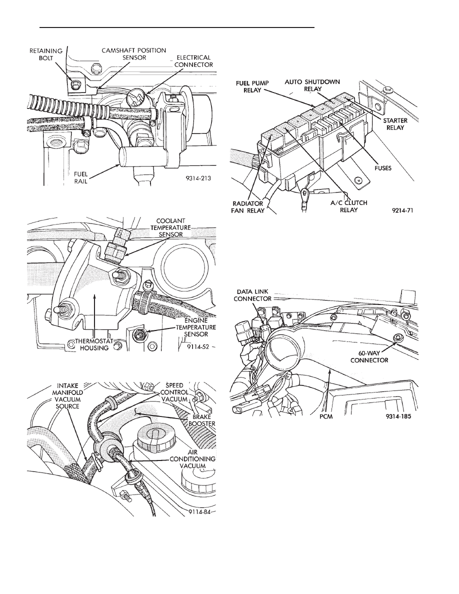
(16) Verify that all electrical connectors are fully
inserted into relays and that battery connections are
clean and tight (Fig. 11).
(17) Check the 60-way electrical connection at the
PCM for damage or spread terminals. Verify that the
60-way connector is fully inserted into the socket on
the PCM (Fig. 12). Ensure that wires are not
stretched or pulled out of the connector.
(18) Verify the harness connector is attached to
idle air control motor (Fig. 13).
(19) Verify the harness connector is attached to
the throttle position sensor (Fig. 13).
(20) Inspect the hose connections at throttle body
(Fig. 13).
(21) Verify all hose connections at the intake man-
ifold are secure (Fig. 14).
(22) Check vacuum hose connection between vac-
uum source and fuel pressure regulator (Fig. 15).
(23) Inspect the charge air temperature sensor
electrical connector (Fig. 15).
Fig. 8 Camshaft Position Sensor Electrical
Connection
Fig. 9 Coolant Temperature and Engine
Temperature Sensor
Fig. 10 Power Brake Booster and Speed Control
Vacuum Hose Connections
Fig. 11 Power Distribution Center
Fig. 12 PCM Electrical Connector
Ä
FUEL SYSTEMS
14 - 97
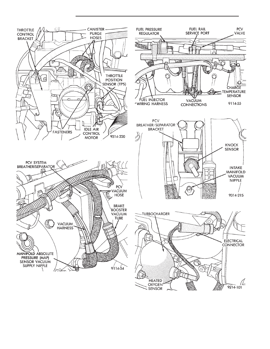
(24) Inspect fuel injectors wiring connectors (Fig.
15).
(25) Inspect the knock sensor electrical connector
(Fig. 16).
(26) Inspect the heated oxygen sensor electrical con-
nector (Fig. 17).
(27) Verify engine ground strap is attached to the
engine and the dash panel.
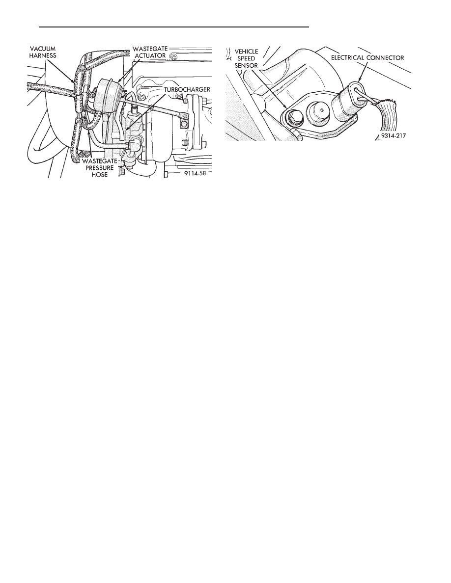
(28) Verify the hose connections on the turbo charger
are secure (Fig. 18).
(29) Check the turbocharger bypass valve hose con-
nections.
(30) Verify 2-way connector is attached to vehicle
speed sensor (Fig. 19).
Fig. 13 Throttle Body Electrical and Vacuum Hose
Connections
Fig. 14 Intake Manifold Vacuum Connections
Fig. 15 Vacuum and Electrical Connections
Fig. 16 Knock Sensor
Fig. 17 Heated Oxygen Sensor
14 - 98
FUEL SYSTEMS
Ä
(31) Check hose and wiring connections at fuel
pump. Check that wiring connector is making con-
tact with terminals on pump.
Fig. 18 Hose Connections
Fig. 19 Vehicle Speed Sensor Wiring Connector
Ä
FUEL SYSTEMS
14 - 99

2.2L TURBO III MULTI-PORT FUEL INJECTION—ON-BOARD DIAGNOSTICS
INDEX
page
page
60-Way PCM Wiring Connector
. . . . . . . . . . . . . 105
Circuit Actuation Test Mode
. . . . . . . . . . . . . . . . 105
Diagnostic Trouble Code Description
. . . . . . . . . 101
General Information
. . . . . . . . . . . . . . . . . . . . . . 100
High and Low Limits
. . . . . . . . . . . . . . . . . . . . . 101
Ignition Timing Procedure
. . . . . . . . . . . . . . . . . 105
Monitored Circuits
. . . . . . . . . . . . . . . . . . . . . . . 100
Non-Monitored Circuits
. . . . . . . . . . . . . . . . . . . 100
State Display Test Mode
. . . . . . . . . . . . . . . . . . 104
System Tests
. . . . . . . . . . . . . . . . . . . . . . . . . . 104
Throttle Body Minimum Air Flow Check
Procedure
. . . . . . . . . . . . . . . . . . . . . . . . . . . . 105
GENERAL INFORMATION
The powertrain control module (PCM) has been pro-
grammed to monitor many different circuits of the fuel
injection system. If a problem is sensed with a moni-
tored circuit often enough to indicate an actual prob-
lem, the PCM stores a fault. If the problem is repaired
or ceases to exist, the PCM cancels the Diagnostic
trouble code after 51 vehicle key on/off cycles.
Certain criteria must be met for a diagnostic trouble
code to be entered into PCM memory. The criteria may
be a specific range of engine RPM, engine temperature,
and/or input voltage to the PCM.
It is possible that a diagnostic trouble code for a
monitored circuit may not be entered into memory
even though a malfunction has occurred. This may
happen because one of the diagnostic trouble code
criteria for the circuit has not been met. For example,
assume that one of the diagnostic trouble code criteria
for a certain sensor circuit is that the engine must be
operating between 750 and 2000 RPM. If the sensor
output circuit shorts to ground when engine RPM is
above 2400 RPM (resulting in a 0 volt input to the
PCM) a diagnostic trouble code will not be entered into
memory. This is because the condition does not occur
within the specified RPM range.
There are several operating conditions for which the
PCM does not monitor and set diagnostic trouble codes.
Refer to Monitored Circuits and Non-Monitored Cir-
cuits in this section.
Stored diagnostic trouble codes can be displayed
either by cycling the ignition key On - Off - On - Off -
On, or through use of the DRB II scan tool. The DRBII
scan tool connects to the data link connector in the
vehicle (Fig. 1).
MONITORED CIRCUITS
The powertrain control module (PCM) can detect
certain fault conditions in the fuel injection system.
Open or Shorted Circuit - The PCM can determine
if the sensor output (input to PCM) is within proper
range. Also, the PCM can determine if the circuit is
open or shorted.
Output Device Current Flow - The PCM senses
whether the output devices are hooked up. If there is
a problem with the circuit, the PCM senses whether
the circuit is open, shorted to ground, or shorted
high.
Oxygen Sensor - The PCM can determine if the
oxygen sensor is switching between rich and lean
once the system has entered closed loop. Refer to
Modes of Operation in this section for an explanation
of closed loop operation.
NON-MONITORED CIRCUITS
The PCM does not monitor the following circuits,
systems and conditions that could have malfunctions
that result in driveability problems. Diagnostic trou-
ble codes may not be displayed for these conditions.
However, problems with these systems may cause di-
agnostic trouble codes to be displayed for other sys-
tems. For example, a fuel pressure problem will not
register a fault directly, but could cause a rich or
lean condition. This could cause an oxygen sensor
fault to be stored in the PCM.
Fuel Pressure - Fuel pressure is controlled by the
fuel pressure regulator. The PCM cannot detect a
clogged fuel pump inlet strainer, clogged in-line fuel
filter, or a pinched fuel supply or return line. How-
ever, these could result in a rich or lean condition
causing an oxygen sensor fault to be stored in the
PCM.
Fig. 1 Data Link Connector Location—AG Body
14 - 100
FUEL SYSTEMS
Ä
Нет комментариевНе стесняйтесь поделиться с нами вашим ценным мнением.
Текст