Chrysler Le Baron, Dodge Dynasty, Plymouth Acclaim. Manual — part 303
AC AND AY BODIES
INDEX
page
page
Electronic Cluster
. . . . . . . . . . . . . . . . . . . . . . . . 34
Gauges
. . . . . . . . . . . . . . . . . . . . . . . . . . . . . . . . 28
General Information
. . . . . . . . . . . . . . . . . . . . . . . 23
Interior Lamp Replacement
. . . . . . . . . . . . . . . . . 41
Mechanical Cluster and Gauge Service
. . . . . . . . 24
Mechanical/Electronic Cluster Removal
. . . . . . . . 25
Switch and Panel Component Service
. . . . . . . . . 37
GENERAL INFORMATION
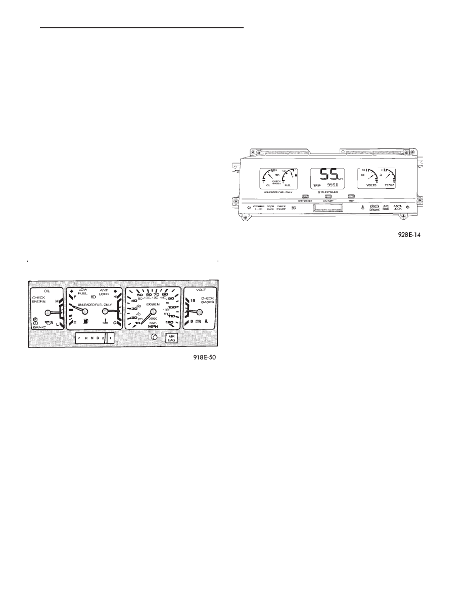
MECHANICAL CLUSTER
The mechanical cluster includes a fuel, oil pres-
sure, coolant temperature, and voltmeter gauges. All
incorporate magnetic type gauges. When the ignition
switch is in the OFF position, the gauges will show a
reading; however, the readings are only accurate
when the ignition switch is in the ON position.
The mechanical cluster also includes an electric
speedometer, driven by pulses from the vehicle speed
sensor (Fig. 1).
ELECTRONIC CLUSTER
The electronic cluster is easily distinguished from
the mechanical cluster by its digital and linear dis-
play. The electronic cluster includes:
• Oil pressure gauge
• Coolant temperature gauge
• Voltmeter
• Fuel gauge
The electronic cluster receives virtually all of its
information to display from the body controller and
powertrain control module via the Chrysler Collision
Detection (CCD) Serial Data Bus. The odometer
memory is no longer retained in the cluster. This is
now retained in the body controller (Fig. 2).
ELECTRONIC CLUSTER DIMMING
The electronic cluster display is dimmed from day-
time to night time intensity when the headlamp
switch is turned on. This intensity can be controlled
using the headlamp switch rheostat.
An additional detent on the headlamp switch rheo-
stat will allow daytime intensity while driving with
headlamps on during the daytime.
WARNING LAMPS
The mechanical instrument cluster will have warn-
ing lamps for six systems. These include brake sys-
tem, air bag, seat belt, low fuel, anti-lock for optional
anti-lock brake system, and malfunction indicator
(check engine) lamp. The cluster also includes check
gages indicator which will illuminate in a warning
situation. This will notify driver to check for a prob-
lem in coolant temperature, oil pressure, or electrical
systems.
The electronic cluster will have warning indicator
lamps for eight different systems. These include:
• Air Bag
• Low washer fluid
• Door/deck lid ajar
• Malfunction Indicator (Check engine) Lamp
• Brake system
• Seat belt
• Anti-lock (ABS) for optional anti-lock brake sys-
tem
• Check gages, monitors engine coolant, oil pressure
and electrical charging system failures.
In addition, ISO symbol will flash to notify the
driver in event of:
• Low fuel
• High temperature
• Low oil pressure
• Charging system failure
Fig. 1 Mechanical Cluster
Fig. 2 Electronic Cluster
Ä
INSTRUMENT PANEL AND GAUGES
8E - 23
MESSAGE CENTER
The message center is a car graphic warning lamp
module. This conventional warning system and lo-
cated above the headlamp switch.
ELECTRONIC DIGITAL CLOCK
The electronic digital clock is in the radio. The
clock and radio each use the display panel built into
the radio. A digital readout indicates the time in
hours and minutes whenever the ignition switch is in
the ON or ACC position.
When the ignition switch is in the OFF position, or
when the radio frequency is being displayed, time
keeping is accurately maintained.
The procedure for setting the clock varies slightly
with each radio. The correct procedure is described
under the individual radio operating instructions re-
ferred to in the Owner’s Manual supplied with the
vehicle.
AIR BAG WARNING SYSTEM
For testing of this system refer to Group 8M, Re-
straint Systems.
MECHANICAL CLUSTER AND GAUGE SERVICE
CAUTION: Disconnect negative battery cable, in en-
gine
compartment,
before
servicing
instrument
panel. When power is required for test purposes,
reconnect battery cable for the test only.
Disconnect negative battery cable after test and be-
fore continuing service procedures.
SENDING UNIT TEST
When a problem occurs with a cluster gauge, be-
fore disassembling the cluster to check the gauge,
check for a defective sending unit or wiring.
(1) Sending units and wiring can be checked by
grounding the connector leads, at the sending unit,
in the vehicle.
(2) With the ignition in the ON position; a
grounded input will cause the oil, fuel or tempera-
ture gauge to read at or above maximum.
CHECK GAUGES WARNING LAMP TESTS
The check gauges warning lamp is illuminated by
the low oil pressure sending unit switch or the body
controller when there is high temperature or charg-
ing system failure.
To test the lamp, turn ignition key to the ON po-
sition without starting the vehicle. The low oil pres-
sure switch is grounded and the light will be on
indefinitely.
If the lamp fails to light, pull the cluster and check
the following:
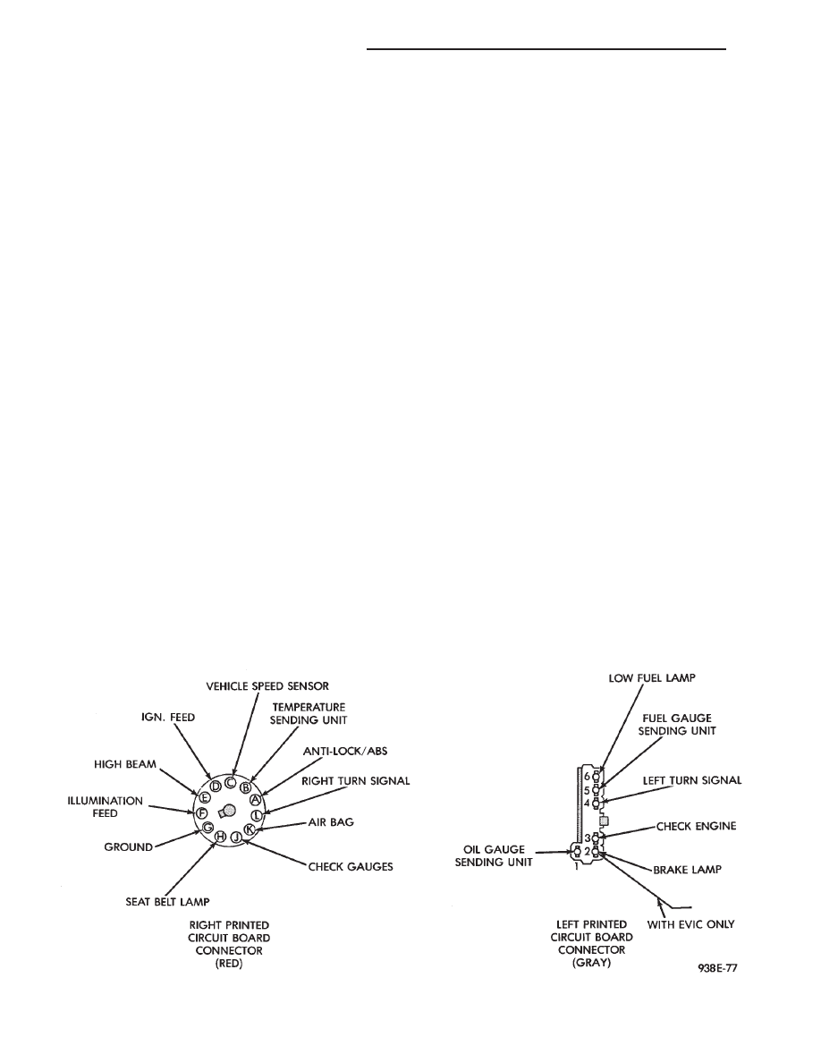
(a) Continuity between ground and check gauge
pin J (Fig. 3).
(b) Proper contact between the gauge pins and
wiring harness and printed circuit board pins.
(c) If there is ground and proper pin contact, re-
place lamp.
(d) If there is no continuity, check the low oil
pressure sending unit switch (Fig. 4 and 5).
To test the switch disconnect the switch electrical
connector. Attach positive lead of an ohmmeter to
the switch terminal for the gray (GY) wire and the
negative lead to an engine ground. With the engine
Fig. 3 Mechanical Cluster Connectors
8E - 24
INSTRUMENT PANEL AND GAUGES
Ä

off, there should be continuity in the system. Start
the engine. With the engine running, the ohmmeter
should show no continuity. If the above results are
not obtained, replace the switch.
BRAKE SYSTEM WARNING LAMP
The brake warning lamp illuminates when parking
brake is applied with ignition key turned ON. The
same lamp will also illuminate should one of the two
service brake systems fail when brake pedal is ap-
plied. To test system turn ignition key ON, and ap-
ply parking brake. If lamp fails to light, inspect for a
burned out lamp, disconnected socket, a broken or
disconnected wire at switch. The lamp also lights
when the ignition switch is turned to START.
To test service brake warning system, raise vehicle
on a hoist and open a wheel cylinder bleeder while a
helper depresses brake pedal and observes warning
light. If lamp fails to light, inspect for a burned out
lamp, disconnected socket, a broken or disconnected
wire at switch.
If lamp is not burned out and wire continuity is
proven, replace brake warning switch in brake line
Tee fitting mounted on frame rail in engine compart-
ment below master cylinder (Fig.6 and 7).
CAUTION: If wheel cylinder bleeder was opened
check master cylinder fluid level.
SEAT BELT WARNING LAMP
For testing of this system, refer to Group 8M, Re-
straint System.
MALFUNCTION INDICATOR (CHECK ENGINE) LAMP
For testing of this system, refer to the Powertrain
Diagnostic Test Procedure Manual.
MECHANICAL/ELECTRONIC CLUSTER REMOVAL
CLUSTER BEZELS REMOVAL
(1) Move gear selector to the low position.
(2) Remove five screws attaching upper bezel to in-
strument panel (Fig. 8).
(3) Lift cluster bezel over steering wheel.
(4) Remove four screws attaching lower bezel to in-
strument panel.
(5) Lift lower cluster bezel from instrument panel.
(6) For installation reverse above procedures.
CLUSTER MASK AND LENS REMOVAL
(1) Remove cluster bezel.
(2) Remove trip reset knob by pulling straight
back.
(3) Remove five screws attaching mask and lens to
cluster.
(4) For installation reverse above procedures.
Fig. 4 Combination Oil Sending Unit
Fig. 5 Combination Oil Sending Unit Test
Fig. 6 Brake Warning Lamp Switch
Ä
INSTRUMENT PANEL AND GAUGES
8E - 25

CLUSTER ASSEMBLY
REMOVAL—CLUSTER WITH TRANSMISSION RANGE
INDICATOR FROM STEERING COLUMN
(1) Disconnect battery to assure no air bag system
fault codes are stored.
(2) Remove cluster bezel (Fig. 9).
Fig. 7 Brake System Warning Lamp Diagnosis
Fig. 8 Cluster Bezel
Fig. 9 Instrument panel Bezels
8E - 26
INSTRUMENT PANEL AND GAUGES
Ä
Нет комментариевНе стесняйтесь поделиться с нами вашим ценным мнением.
Текст