Chrysler Le Baron, Dodge Dynasty, Plymouth Acclaim. Manual — part 161

HOOD INSTALLATION
Reverse the preceding operation.
HOOD HINGE REMOVAL (FIG. 3)
(1) Support hood on the side that requires hinge
replacement.
(2) Mark all bolt and hinge attachment locations
with a grease pencil or other suitable device to pro-
vide reference marks for installation. When install-
ing hood hinge, align all marks and secure bolts. The
hood should be aligned to 4 mm (0.160 in.) gap to the
front fenders and flush across the top surfaces along
fenders. Shims can be added or removed under hood
hinge to achieve proper hood height.
(3) Remove hood to hinge attaching bolts.
(4) Remove hood hinge to front fender attaching
bolts and separate hinge from vehicle.
HOOD HINGE INSTALLATION
Reverse the preceding operation. If necessary, paint
new hinge before installation.
HOOD LATCH AND RELEASE CABLE
HOOD LATCH REMOVAL (FIG. 4)
(1) Raise hood to the full up position.
(2) Remove radiator closure panel sight shield.
(3) Remove hood latch attaching bolts holding
latch to radiator closure panel and separate from ve-
hicle.
(4) Pry release cable casing attachment from slot
receiver on latch, disengage cable end from latch arm
hook.
HOOD LATCH INSTALLATION
Reverse the preceding operation.
HOOD LATCH RELEASE CABLE REMOVAL
(FIG. 5)
(1) Raise hood to the full up position.
(2) Remove push-in fasteners holding sight shield
to radiator closure panel and separate cover from ve-
hicle.
(3) Disconnect hood release cable casing and cable
end from hood latch assembly. Refer to Hood Latch
Removal procedure in this section.
Fig. 2 Hood Assembly Remove or Install—Typical
Fig. 3 Hood Hinge Assembly—Typical
Fig. 4 Hood Latch Assembly—Typical
Ä
AG-BODY
23 - 53
(4) Remove hood latch release cable handle attach-
ing bolts from under left lower edge of instrument
panel.
(5) Disengage release cable rubber grommet from
engine compartment dash panel behind instrument
panel.
(6) Rout cable assembly through engine compart-
ment around battery, under fender lip, under power
distribution center, and under wiring harnesses, to-
ward dash panel. Push cable through access hole in
dash panel under the brake master cylinder, into
passenger compartment.
HOOD LATCH RELEASE CABLE
INSTALLATION
Reverse the preceding operation.
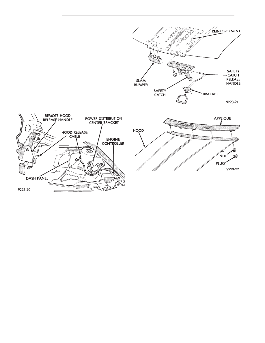
HOOD LATCH SAFETY CATCH
REMOVAL (FIG. 6)
(1) Raise hood to full up position.
(2) Remove screw holding safety latch handle
bracket to hood.
(3) Mark location of safety catch on hood to assist
installation alignment.
(4) Remove bolts holding safety catch to hood.
(5) Separate safety catch from hood.
INSTALLATION
Reverse the preceding operation.
HOOD APPLIQUE
REMOVAL (FIG. 7)
(1) Raise hood to full up position.
(2) Remove plugs from access holes at rear of hood.
(3) Remove nuts holding applique to hood.
(4) Separate applique from hood.
INSTALLATION
Reverse the preceding operation.
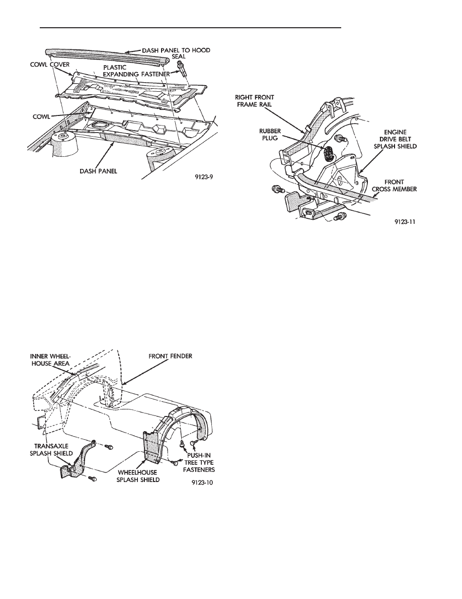
COWL COVER
REMOVAL (FIG. 8)
(1) Raise hood to full up position.
(2) Disconnect windshield washer hoses from wiper
arms.
(3) Remove windshield wiper arm assemblies. Re-
fer to Group 8K, Windshield Wiper and Washer Sys-
tems.
(4) Remove plastic expanding type fasteners hold-
ing cowl cover to cowl, below windshield.
(5) Lift back of cowl cover and slide cover rearward
from under dash panel to hood seal and separate
cover from vehicle.
INSTALLATION
Reverse the preceding operation.
FRONT END SPLASH SHIELDS
REMOVAL (FIG. 9)
(1) Hoist vehicle and support on suitable safety
stands.
(2) Remove front wheel assembly.
(3) Remove push-in fasteners holding front wheel-
house splash shield to fender opening lip and inner
wheelhouse area.
Fig. 5 Hood Latch Release Cable
Fig. 6 Hood Latch Safety Catch
Fig. 7 Hood Applique
23 - 54
AG-BODY
Ä
(4) Separate wheelhouse splash shield from vehi-
cle.
INSTALLATION
Reverse the preceding operation.
TRANSAXLE SPLASH SHIELD REMOVAL (FIG.
9)
(1) Remove one front wheelhouse splash shield
push-in fastener and separate wheelhouse splash
shield from transaxle splash shield.
(2) Remove transaxle splash shield attaching bolts
and separate transaxle splash shield from vehicle.
TRANSAXLE SPLASH SHIELD INSTALLATION
Reverse the preceding operation.
ENGINE DRIVE BELT SPLASH SHIELD
REMOVAL (FIG. 10)
(1) Hoist vehicle and support on suitable safety
stands.
(2) Remove bolts holding engine drive belt splash
shield to right frame rail.
(3) Separate drive belt splash shield from vehicle.
ENGINE DRIVE BELT SPLASH SHIELD
INSTALLATION
Reverse the preceding operation.
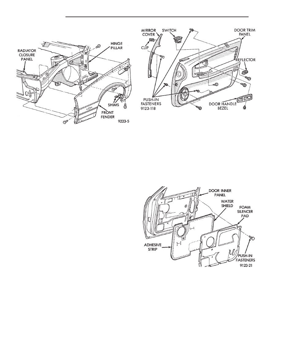
FRONT FENDER
REMOVAL (FIG. 11)
(1) Remove front side marker lamp assembly. Re-
fer to Group 8L, Lamps for instructions.
(2) Remove front bumper as necessary to gain
clearance to remove front fender. Refer to Front
Bumper Removal paragraph in this section.
(3) Remove front wheelhouse splash shield. Refer
to Front Wheelhouse Splash Shield Removal para-
graph of this section.
(4) Remove side applique as necessary to clear
front fender. Refer to Body Side Applique Removal
paragraph in this section.
(5) Remove bolts holding bottom of front fender at
rear of wheel opening.
(6) Remove bolt holding front fender to hinge pil-
lar at rear of wheelhouse.
(7) Remove bolt holding front fender to cowl at top
of front door opening.
(8) Remove bolts holding front fender to underside
of radiator closure panel.
(9) Remove bolts holding front fender to front of
radiator closure panel.
(10) Raise hood and support hood on a suitable
holding device. Mark hinge for installation indexing.
Remove lower hood hinge attaching bolts and sepa-
rate hinge from front fender. Refer to Hood Hinge
Removal paragraph in this section.
(11) Remove bolts holding front fender to inner
wheelhouse along hood opening.
(12) Separate front fender from vehicle.
INSTALLATION
Reverse the preceding operation. Align front fender
to achieve a 4 mm (0.160 in) gap to hood edge and 6
Fig. 8 Cowl Cover Assembly
Fig. 9 Front Wheelhouse and Transaxle Splash
Shields—Typical
Fig. 10 Engine Drive Belt Splash Shield—Typical
Ä
AG-BODY
23 - 55
mm (0.240 in) gap to front door edge. All surfaces
across gaps should be flush.
DOOR TRIM PANEL
REMOVAL (FIG. 12)
(1) Lower door glass to down position. Disconnect
battery negative cable, if equipped with power win-
dows.
(2) Remove window crank screw cover. Remove
screw holding window crank to regulator and sepa-
rate crank from door, if equipped with manual win-
dows.
(3) Remove screw holding inside latch release han-
dle bezel to door. Slide bezel forward and remove
from door panel. Disconnect power door lock switch
wire connector, if equipped.
(4) Pull power mirror switch outward to disengage
clips holding switch to door panel. Disconnect mirror
switch wire connector, if equipped.
(5) Lift upward at rear edge of power window/seat
switch bezel to disengage clips holding bezel to door
panel. Disconnect wire connectors from power win-
dow and power seat switches, if equipped.
(6) Remove screw holding trim panel to door from
inside power window switch bezel opening.
(7) Pry outward on reflector lens to disengage
clips. Remove screw holding trim panel to door from
behind reflector.
(8) Remove hidden screws holding trim panel to
door from carpet area on trim panel.
(9) Disengage push-in fasteners holding trim panel
to door at ends and bottom center of trim panel.
(10) Lift trim panel from door.
INSTALLATION
Reverse the preceding operation.
FRONT DOOR SILENCER AND WATER SHIELD
REMOVAL (FIG. 13)
(1) Remove front door trim panel.
(2) Remove push-in fasteners holding silencer pad
to door inner panel and separate silencer from door.
(3) Pull water shield from adhesive around perim-
eter of door inner panel.
INSTALLATION
Reverse the preceding operation.
FRONT DOOR AND HINGE
The front door hinge is welded to the door and
bolted to the hinge pillar. The door half of the hinge
pivots on a removable hinge pin. The hinge pin is
driven in from the bottom on the top hinge and from
the top on the bottom hinge. All adjustments to the
hinge are performed on the hinge pillar half of the
hinge. If the welded half of the hinge must be bent to
align door, consult an authorized body repair facility.
Fig. 11 Front Fender
Fig. 12 Door Trim Panel
Fig. 13 Front Door Silencer and Water
Shield—Typical
23 - 56
AG-BODY
Ä
Нет комментариевНе стесняйтесь поделиться с нами вашим ценным мнением.
Текст