Chrysler Le Baron, Dodge Dynasty, Plymouth Acclaim. Manual — part 17

FRONT BUMPER ASSEMBLY
Reverse the preceding operation.
FRONT BUMPER AND FASCIA REMOVAL—AC/
C-BODY (FIG. 5)
(1) Raise vehicle and support on safety stands.
(2) Remove push-in fasteners holding bumper fas-
cia to front wheel opening lip.
(3) Support bumper on a suitable lifting device.
(4) Remove nuts holding bumper reinforcement to
energy absorbers.
(5) Separate bumper from vehicle.
INSTALLATION
Reverse the preceding operation.
BUMPER OVERHAUL—AC/C-BODY
(1) Position bumper assembly on a suitable padded
work surface to avoid damage to painted fascia.
(2) Remove bolts holding bumper face bar to rein-
forcement.
(3) Remove push-in fasteners holding fascia to re-
inforcement.
(4) Separate reinforcement from fascia.
BUMPER ASSEMBLY
Reverse the preceding operation.
AG-VEHICLE FRONT BUMPER
FRONT BUMPER FASCIA REMOVAL (FIG. 6)
(1) Remove headlamp and fog lamp (if equipped)
assemblies, refer to Group 8L, Lamps.
(2) Raise vehicle and support on safety stands.
(3) Remove radiator closure panel sight shield.
(4) Remove push-in fasteners holding fascia to
front fender wheel opening flange.
(5) Remove nuts holding fascia to fender from
above side marker reflectors. Remove fender splash
shields if necessary.
(6) Remove nuts holding front fascia headlamp
mounting panel to forward edge of fenders.
(7) Remove bolts holding fascia headlamp mount-
ing panel to radiator closure panel brace.
(8) Remove push-in fasteners holding fascia to bot-
tom of bumper reinforcement.
(9) Separate front bumper fascia and headlamp
mounting panel from vehicle.
INSTALLATION
Reverse the preceding operation. If headlamps re-
quire aiming, refer to Group 8L, Lamps.
HEADLAMP MOUNTING PANEL
REMOVAL—AG-VEHICLE (FIG. 7)
(1) Remove all lamp assemblies, refer to group 8L,
Lamps.
(2) Remove front bumper fascia.
(3) Remove
bolts
holding
fascia
to
headlamp
mounting panel ends.
(4) Remove push-in fasteners holding fascia to
headlamp mounting panel.
(5) Separate headlamp mounting panel from fascia.
INSTALLATION
Reverse the preceding operation
Fig. 4 Front Bumper—AC\ or AC/C-H-Body
Fig. 5 Front Bumper—AC/C-Body
Fig. 6 Front Bumper Fascia—AG-Vehicle
Ä
FRAME AND BUMPERS
13 - 3

FRONT BUMPER REINFORCEMENT
REMOVAL—AG-VEHICLE (FIG. 8)
(1) Remove bumper fascia as necessary to gain
clearance to remove bumper reinforcement.
(2) Remove nuts holding bumper reinforcement to
energy absorber units.
(3) Separate bumper reinforcement from vehicle.
carriage
INSTALLATION
Reverse the preceding operation
FRONT BUMPER ENERGY ABSORBER
REMOVAL—AG-VEHICLE (FIG. 8)
(1) Remove front fascia and bumper reinforcement
as necessary to remove absorber unit.
(2) Remove bolts holding energy absorber unit to
front closure panel.
(3) Separate energy absorber from vehicle.
FRONT BUMPER ENERGY ABSORBER
INSTALLATION
Reverse the preceding operation.
AJ-VEHICLE FRONT BUMPER AND FASCIA
REMOVAL (FIG. 9)
(1) Remove socket and bulb from park and turn
lamp.
(2) Remove nuts holding fascia to fender, from be-
hind forward flange of fender.
(3) Support front bumper assembly on suitable lift-
ing device and remove bolts holding bumper rein-
forcement to energy absorber units.
INSTALLATION
Reverse the preceding operation. Align bumper
height to approximately 5 mm (0.200 in.) gap to bot-
tom of grille and flush to front fenders on the sides.
AP-VEHICLE FRONT BUMPER
REMOVAL (FIG. 10)
(1) Raise vehicle and support on safety stands.
(2) Disconnect front park and turn signal lamp
wire connector.
(3) Remove front side marker lamp socket from
lamp assembly and position socket out of the way.
(4) Remove bolt holding front bumper fascia to
wheelhouse splash shield.
(5) Remove nuts holding fascia to front fender.
(6) Support front bumper on lifting device.
(7) Remove bolts holding front bumper reinforce-
ment to energy absorber units.
(8) Separate front bumper from vehicle.
INSTALLATION
Reverse the preceding operation.
Fig. 7 Headlamp Mounting Panel—AG-Vehicle
Fig. 8 Front Bumper Reinforcement and Energy
Absorber Unit—
Fig. 9 Front Bumper and Fascia—AJ-Vehicle
13 - 4
FRAME AND BUMPERS
Ä

AY-VEHICLE FRONT BUMPER
BUMPER AND FASCIA REMOVAL—AY/P-BODY
(FIG. 11)
(1) Remove wheel house splash shields as neces-
sary to gain access to fascia attaching nuts.
(2) Remove lower fascia bottom extension cover.
(3) Remove nuts holding fascia to fender, from be-
hind forward flange of fender.
(4) Support front bumper assembly on suitable lift-
ing device.
(5) Remove nuts holding bumper to energy ab-
sorber units.
(6) Separate bumper from vehicle.
INSTALLATION
Reverse the preceding operation. Align bumper
height to fit flush to bottom of filler panel.
FRONT BUMPER AND FASCIA REMOVAL—AY/
S-BODY (FIG. 12)
(1) Raise vehicle and support on safety stands.
(2) Remove push-in fasteners holding bumper fas-
cia to front wheel opening lip.
(3) Support bumper on a suitable lifting device.
(4) Remove nuts holding bumper reinforcement to
energy absorbers.
(5) Separate bumper from vehicle.
INSTALLATION
Reverse the preceding operation.
BUMPER OVERHAUL—AY/S BODY
(1) Position bumper assembly on a suitable padded
work surface to avoid damage to painted fascia.
(2) Remove bolts holding bumper face bar to rein-
forcement.
(3) Remove push-in fasteners holding fascia to re-
inforcement.
(4) Separate reinforcement from fascia.
BUMPER ASSEMBLY
Reverse the preceding operation.
AA-VEHICLE REAR BUMPER
REAR BUMPER AND STANDARD FASCIA
REMOVAL (FIG. 13)
(1) Open trunk lid and separate quarter panel lin-
ers (if equipped) from tail panel area.
(2) Remove rear fascia attaching nuts at rear of in-
ner quarter panel drop-down wells.
(3) Remove lower fascia push-in fasteners holding
fascia to bottom of bumper reinforcement.
(4) Remove fascia nuts holding fascia to trunk
opening panel.
(5) Remove fascia bolts holding fascia to ends of
bumper reinforcement.
(6) Separate fascia from reinforcement and sepa-
rate fascia from vehicle.
(7) Support bumper reinforcement. Remove rein-
forcement attaching bolts and separate assembly
from energy absorbers.
INSTALLATION
Reverse the preceding operation.
Fig. 10 Front Bumper—AP-Vehicle
Fig. 11 Front Bumper and Fascia—AY/P-Body
Fig. 12 Front Bumper—AY/S-Body
Ä
FRAME AND BUMPERS
13 - 5
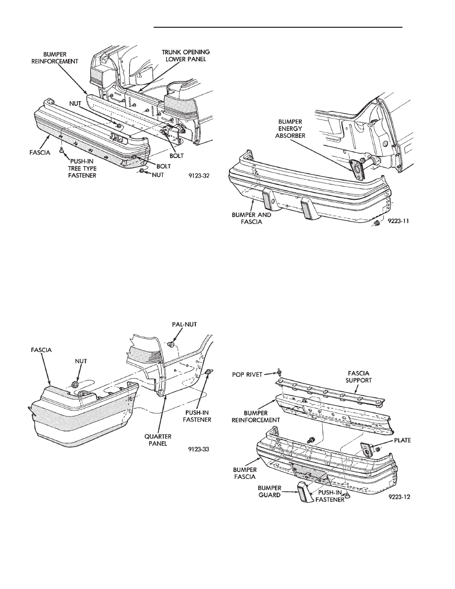
REAR BUMPER AND WRAP-AROUND FASCIA
REMOVAL (FIG. 14)
(1) Remove push-in fasteners holding rear fascia to
rearward edge of wheel opening.
(2) Open trunk lid and separate quarter panel
liner from tail panel area ,if equipped.
(3) Remove pal-nut fasteners located behind quar-
ter panel, holding fascia to quarter panel.
(4) Perform steps 2 through 7 of Rear Bumper and
Standard Fascia Removal/Installation procedure.
INSTALLATION
Reverse the preceding operation.
AC-VEHICLE REAR BUMPER
REAR BUMPER REMOVAL—AC/D-BODY (FIG.
15)
(1) Disconnect license plate lamps wire connectors.
(2) Remove nuts holding fascia to quarter panel
ends.
(3) Support bumper assembly on suitable lifting
device and remove bolts holding bumper reinforce-
ment to energy absorber units.
(4) Separate bumper from vehicle.
INSTALLATION
Reverse the preceding operation. Align bumper
height to fit flush to bottom of tail lamp.
REAR BUMPER OVERHAUL—AC/D-BODY (FIG.
16)
(1) Position bumper assembly on a suitable padded
work surface to avoid damage to painted fascia.
(3) Remove push-in fasteners holding fascia to bot-
tom of reinforcement.
(4) Remove bolts holding fascia to reinforcement
and separate fascia from reinforcement.
(5) Remove bolts holding bumper guards to fascia
and separate guards from fascia.
REAR BUMPER ASSEMBLY
Reverse the preceding operation.
REAR BUMPER REMOVAL
AC/C-BODY (FIG. 17)
(1) In luggage compartment, separate liners from
quarter panels to gain access to fascia nuts.
Fig. 13 Standard Rear Bumper—AA-Vehicle
Fig. 14 Wrap-around Rear Bumper—AA-Vehicle
Fig. 15 Rear Bumper—AC/D-Body
Fig. 16 Rear Bumper Overhaul—AC/D-Body
13 - 6
FRAME AND BUMPERS
Ä
Нет комментариевНе стесняйтесь поделиться с нами вашим ценным мнением.
Текст