Chrysler Le Baron, Dodge Dynasty, Plymouth Acclaim. Manual — part 270
STARTER TEST PROCEDURES ON VEHICLE
INDEX
page
page
Diagnostic Preparation
. . . . . . . . . . . . . . . . . . . . . 11
General Information
. . . . . . . . . . . . . . . . . . . . . . . 11
Starter Control Circuit Tests
. . . . . . . . . . . . . . . . 15
Starter Feed Circuit Tests
. . . . . . . . . . . . . . . . . . 11
GENERAL INFORMATION
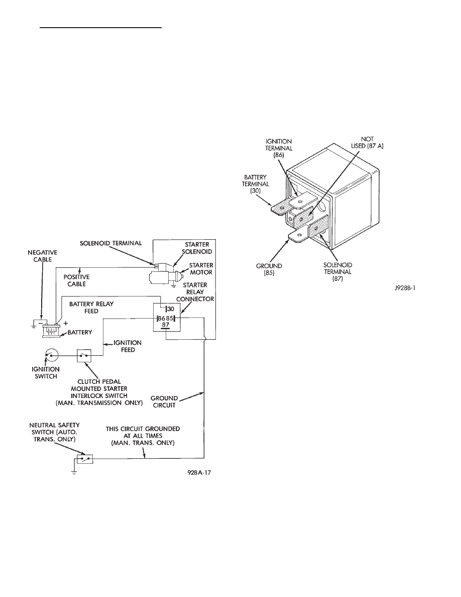
The starting system (Fig. 1) has:
• Ignition switch
• Starter relay (Fig. 2)
• Neutral starting and back-up switch with auto-
matic transmissions
• Clutch pedal mounted starter interlock switch
with manual transmissions
• Wiring harness
• Battery
• Starter motor with an integral solenoid
These components form two separate circuits. A
high amperage circuit that feeds the starter motor up
to 300+ amps, and a control circuit that operates on
less than 20 amps.
DIAGNOSTIC PREPARATION
Before going on with starting system diagnostics,
verify:
(1) The battery top, posts, and terminals are clean.
(2) The generator drive belt tension and condition
is correct.
(3) The battery state-of-charge is correct.
(4) The battery will pass load test.
(5) The battery cable connections at the starter
and engine block are clean and free from corrosion.
(6) The wiring harness connectors and terminals
are clean and free from corrosion.
(7) Proper circuit grounding.
(8) Refer to Starter System Diagnostics (Fig. 3).
STARTER FEED CIRCUIT TESTS
The following procedure will require a suitable
volt/ampere tester (Fig. 4).
CAUTION: Ignition system also must be disabled to
prevent engine start while performing the following
tests.
(1) Connect a volt-ampere tester (Fig. 4) to the bat-
tery terminals (Fig. 5). Refer to the operating in-
structions provided with the tester being used.
(2) Disable ignition system as follows:
• VEHICLES WITH CONVENTIONAL DISTRIBU-
TORS: Disconnect the ignition coil cable from the
distributor cap. Connect a suitable jumper wire be-
tween the coil cable end-terminal and a good body
ground (Fig. 6).
Fig. 1 Starting Components/Wiring
Fig. 2 Starter Relay
Ä
BATTERY/STARTING/CHARGING SYSTEMS DIAGNOSTICS
8A - 11
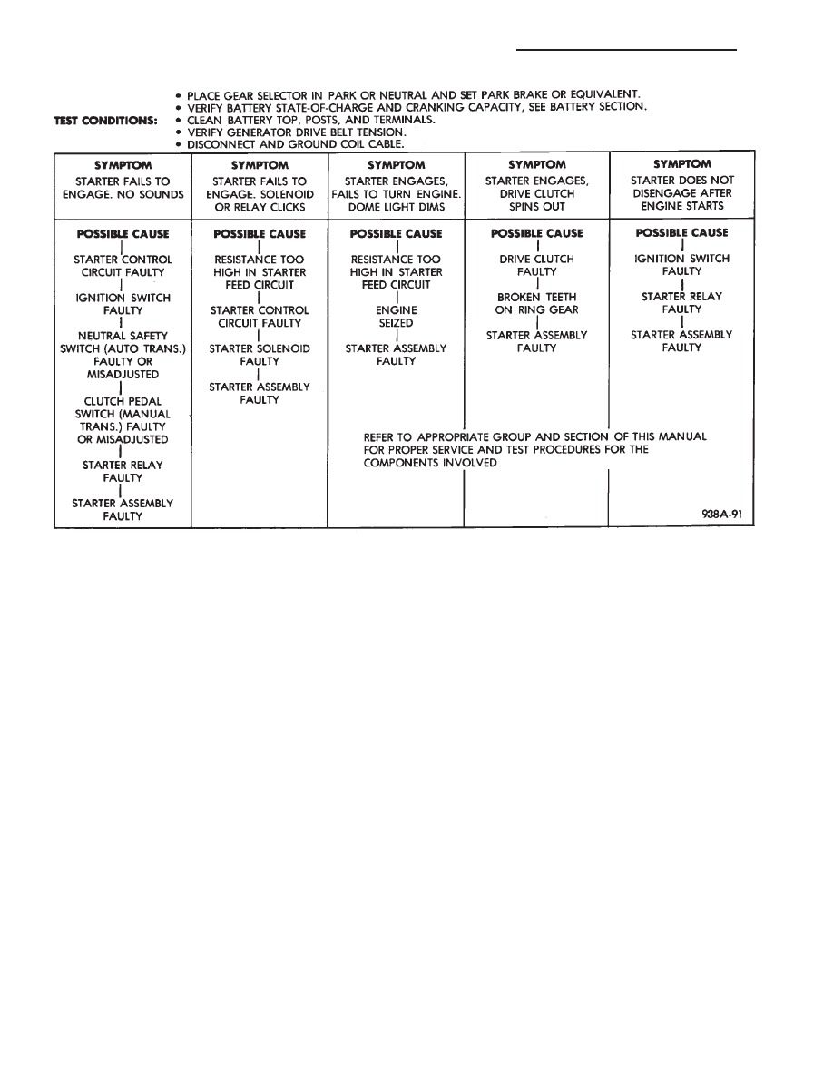
Fig. 3 Starter System Diagnostics
8A - 12
BATTERY/STARTING/CHARGING SYSTEMS DIAGNOSTICS
Ä
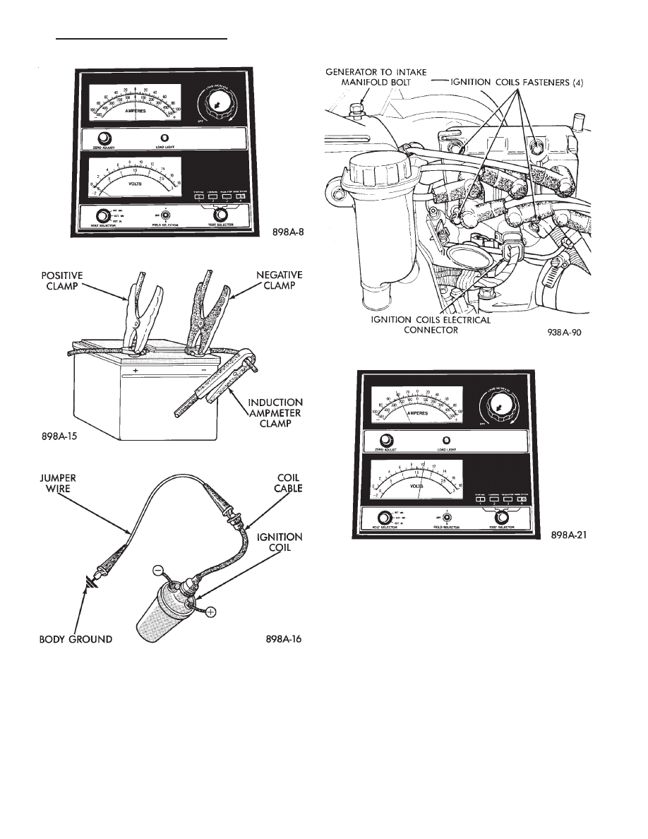
• VEHICLES WITH DIRECT IGNITION SYSTEM:
Disconnect the ignition coils electrical connector (Fig.
7).
(3) Verify that all lights and accessories are OFF,
and the transmission shift selector is in PARK or
manual in NEUTRAL. Set parking brake.
(4) Rotate and hold the ignition switch in the
START position. Observe the volt-ampere tester (Fig.
8).
• If voltage reads above 9.6 volts, and amperage
draw reads above 250 amps, go to the starter feed
circuit resistance test.
• If voltage reads 12.4 volts or greater and amperage
reads 0 to 10 amps, go to starter control circuit test.
CAUTION: Do not overheat the starter motor or
draw the battery voltage below 9.6 volts during
cranking operations.
(5) After the starting system problems have been
corrected, verify the battery state of charge and
charge battery if necessary. Disconnect all testing
equipment and connect ignition coil cable or ignition
coil connector. Start the vehicle several times to as-
sure the problem was corrected.
Fig. 4 Volt Ampere Tester
Fig. 5 Volt-Ampere Tester Connections
Fig. 6 Ground Ignition Coil Cable
Fig. 7 Ignition Coils Electrical Connection
Fig. 8 Starter Draw Tests
Ä
BATTERY/STARTING/CHARGING SYSTEMS DIAGNOSTICS
8A - 13
STARTER FEED CIRCUIT RESISTANCE TEST
Before going on with this operation, review Diag-
nostic Preparation and Starter Feed Circuit Tests.
The following operation will require a voltmeter, ac-
curate to 1/10 of a volt.
CAUTION: Ignition system also must be disabled to
prevent engine start while performing the following
tests.
(1) Disable ignition system as follows:
• VEHICLES WITH CONVENTIONAL DISTRIBU-
TORS: Disconnect the ignition coil cable from the
distributor cap. Connect a suitable jumper wire be-
tween the coil cable end-terminal and a good body
ground (Fig. 6).
• VEHICLES WITH DIRECT IGNITION SYSTEM:
Disconnect the ignition coils electrical connector (Fig.
7).
(2) With all wiring harnesses and components
properly connected, perform the following:
(a) Connect the negative lead of the voltmeter to
the negative battery post, and positive lead to the
negative battery cable clamp (Fig. 9). Rotate and
hold the ignition switch in the START position.
Observe the voltmeter. If voltage is detected, cor-
rect poor contact between cable clamp and post.
(b) Connect positive lead of the voltmeter to the
positive battery post, and negative lead to the pos-
itive battery cable clamp. Rotate and hold the igni-
tion switch key in the START position. Observe the
voltmeter. If voltage is detected, correct poor con-
tact between the cable clamp and post.
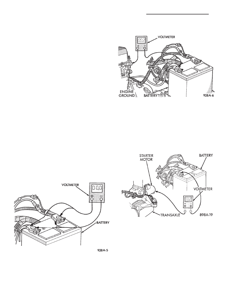
(c) Connect negative lead of voltmeter to nega-
tive battery terminal, and positive lead to engine
block near the battery cable attaching point (Fig.
10). Rotate and hold the ignition switch in the
START position. If voltage reads above 0.2 volt,
correct poor contact at ground cable attaching
point. If voltage reading is still above 0.2 volt after
correcting poor contacts, replace ground cable.
(3) Remove starter heat shield. Refer to Starter re-
placement to gain access to the starter motor and so-
lenoid connections. Perform the following steps:
(a) Connect positive voltmeter lead to the starter
motor housing and the negative lead to the nega-
tive battery terminal (Fig. 11). Hold the ignition
switch key in the START position. If voltage reads
above 0.2 volt, correct poor starter to engine
ground.
(b) Connect the positive voltmeter lead to the
positive battery terminal, and negative lead to bat-
tery cable terminal on starter solenoid (Fig. 12).
Rotate and hold the ignition switch key in the
START position. If voltage reads above 0.2 volt,
correct poor contact at battery cable to solenoid
connection. If reading is still above 0.2 volt after
correcting poor contacts, replace positive battery
cable.
(c) If resistance tests do not detect feed circuit
failures, remove the starter motor and go to Bench
Testing Starter Solenoid.
Fig. 9 Test Battery Connection Resistance
Fig. 10 Test Ground Circuit Resistance
Fig. 11 Test Starter Motor Ground
8A - 14
BATTERY/STARTING/CHARGING SYSTEMS DIAGNOSTICS
Ä
Нет комментариевНе стесняйтесь поделиться с нами вашим ценным мнением.
Текст