Chrysler Le Baron, Dodge Dynasty, Plymouth Acclaim. Manual — part 216
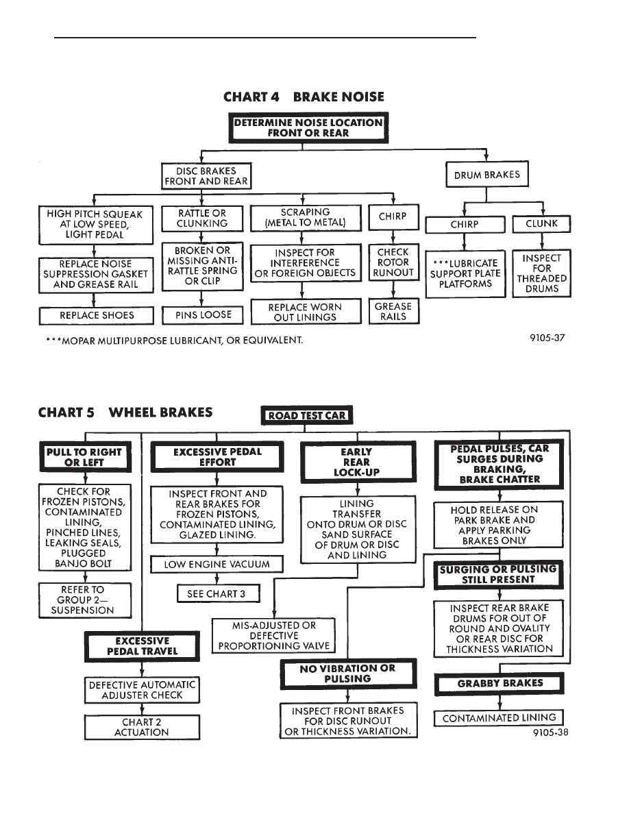
BRAKE SYSTEM DIAGNOSTICS
BRAKE SYSTEM DIAGNOSTICS
Ä
BRAKES
5 - 17
REAR WHEEL DRUM BRAKES
INDEX
page
page
Brake Drum Refacing
. . . . . . . . . . . . . . . . . . . . . 21
Brake Shoe Assemblies
. . . . . . . . . . . . . . . . . . . 19
Description
. . . . . . . . . . . . . . . . . . . . . . . . . . . . . 18
Service Procedures
. . . . . . . . . . . . . . . . . . . . . . . 18
DESCRIPTION
Rear wheel drum brakes (Fig. 2 & 3) are two shoe,
internal expanding type with an automatic adjuster
screw assembly that is activated each time the
brakes are applied. The automatic adjuster screw is
located directly below the wheel cylinder as shown in
figure (Fig. 2 & 3).
WARNING: DUST AND DIRT ON BRAKE PARTS
GENERATED DURING THE NORMAL USE AND
WEAR OF MOTOR VEHICLE BRAKE SYSTEMS MAY
CONTAIN ASBESTOS FIBERS. BREATHING EXCES-
SIVE CONCENTRATIONS OF ASBESTOS FIBERS
CAN CAUSE SERIOUS BODILY HARM, SUCH AS
ASBESTOSIS
AND
CANCER.
EXTREME
CARE
SHOULD
BE
EXERCISED
WHILE
SERVICING
BRAKE ASSEMBLIES OR COMPONENTS.
DO NOT CLEAN BRAKE ASSEMBLIES OR COM-
PONENTS WITH COMPRESSED AIR OR BY DRY
BRUSHING; USE A VACUUM CLEANER SPECIFI-
CALLY RECOMMENDED FOR USE WITH ASBES-
TOS FIBERS. IF A SUITABLE VACUUM CLEANER IS
NOT AVAILABLE, CLEANING SHOULD BE DONE
WET USING A WATER DAMPENED CLOTH.
DO NOT CREATE DUST BY SANDING, GRINDING,
AND/OR SHAVING BRAKE LININGS OR PADS UN-
LESS SUCH OPERATION IS DONE WHILE USING
PROPERLY EXHAUST VENTILATED EQUIPMENT.
DISPOSE OF ALL DUST AND DIRT SUSPECTED
TO CONTAIN ANY ASBESTOS FIBERS IN SEALED
BAGS OR CONTAINERS TO MINIMIZE DUST EXPO-
SURE TO YOURSELF AND OTHERS.
FOLLOW ALL RECOMMENDED PRACTICES PRE-
SCRIBED BY THE OCCUPATIONAL SAFETY AND
HEALTH ADMINISTRATION AND THE ENVIRON-
MENTAL PROTECTION AGENCY. FOR THE HAN-
DLING, PROCESSING, AND DISPOSITION OF DUST
OR DIRT WHICH MAY CONTAIN ASBESTOS FI-
BERS.
IT IS RECOMMENDED NOT TO BREATH ANY
TYPE OF BRAKE LINING MATERIAL DUST EVEN
ASBESTOS FREE, DUE TO THE FIBROUS NATURE
OF THE MATERIALS BEING USED.
SERVICE PROCEDURES
REAR BRAKE DRUM REMOVAL
If the rear brake drum is difficult to remove, fur-
ther clearance can be obtained by backing off the
brake automatic adjuster screw. Remove rubber plug
from the top of the support plate and rotate the au-
tomatic adjuster screw assembly with an upward mo-
tion, using the Brake Adjuster, Special Tool C-3784.
See adjusting rear service brakes in the Service
Adjustments section in this group of the service man-
ual for the specific adjustment procedure.
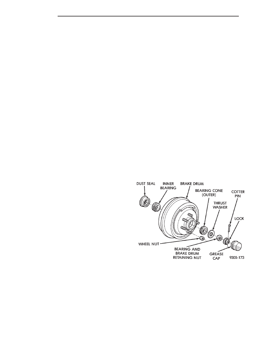
Remove wheel bearing grease cap (Fig. 1).
Remove cotter pin, nut lock, retaining nut, thrust
washer and outer bearing cone (Fig. 1).
Remove brake drum and hub and bearing assembly
from the rear spindle (Fig. 1).
Inspect brake linings for wear, shoe alignment and
contamination.
BRAKE DRUM INSTALLATION
Install brake drum and hub and bearing assembly
on rear spindle.
Install outer wheel bearing, thrust washer and nut.
Tighten wheel bearing adjusting nut to 27 to 34
N
Im (240 to 300 in. lbs.) torque while rotating hub.
This seats the bearings.
Back off adjusting nut 1/4 turn (90°) then tighten
adjusting nut finger tight.
Position lock on nut with one pair of slots in-line
with cotter pin hole. Install cotter pin.
Fig. 1 Brake Drum and Hub Assembly
5 - 18
BRAKES
Ä
Install grease cap and wheel and tire assemblies.
Tighten wheel stud nuts to 115 N
Im (85 ft. lbs.)
torque on all models. Install wheel covers.
BRAKE SHOE ASSEMBLIES
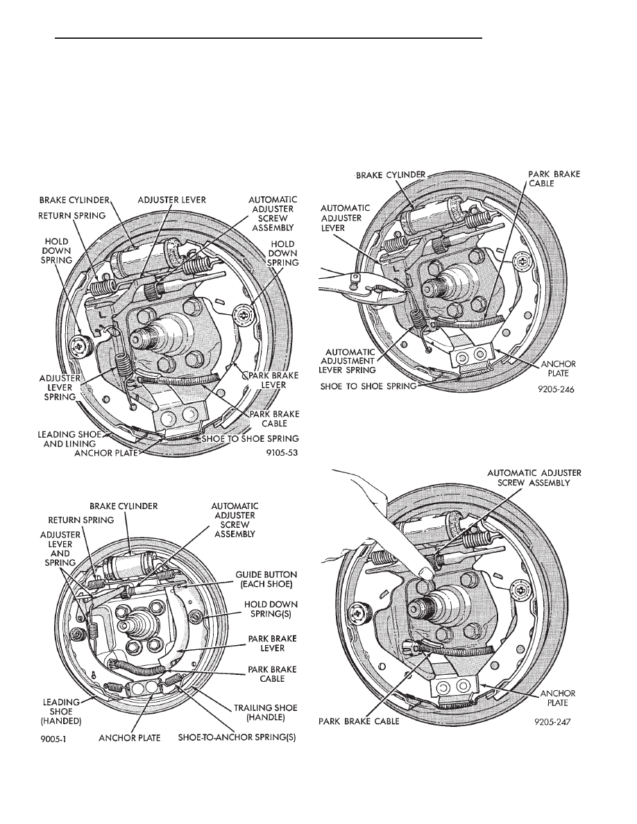
Three brake shoe assemblies are used on the front
wheel drive passenger cars. Vehicles will have axle
sets of either 200 or 220 mm Kelsey Hayes (Fig. 2),
or Varga (Fig. 3). Varga brake shoes are HANDED
for right or left side.
Except for brake shoe to support plate, park brake
lever retention and automatic adjuster positioning
guide buttons, service procedures for either assembly
are essentially the same.
REMOVAL
Remove automatic adjuster spring and lever (Fig.
4).
Rotate the automatic adjuster screw assembly so
that each shoe assembly moves out far enough to be
free from the wheel cylinder boots (Fig. 5).
Disconnect the parking brake cable from the park-
ing brake lever (Fig. 6).
Fig. 2 Kelsey Hayes 200 And 220 (Left) Rear Wheel
Brake
Fig. 3 Varga (Left) Rear Wheel Brake
Fig. 4 Remove or Install Adjuster Lever Spring
Fig. 5 Expand or Retract Adjuster Screw
Ä
BRAKES
5 - 19
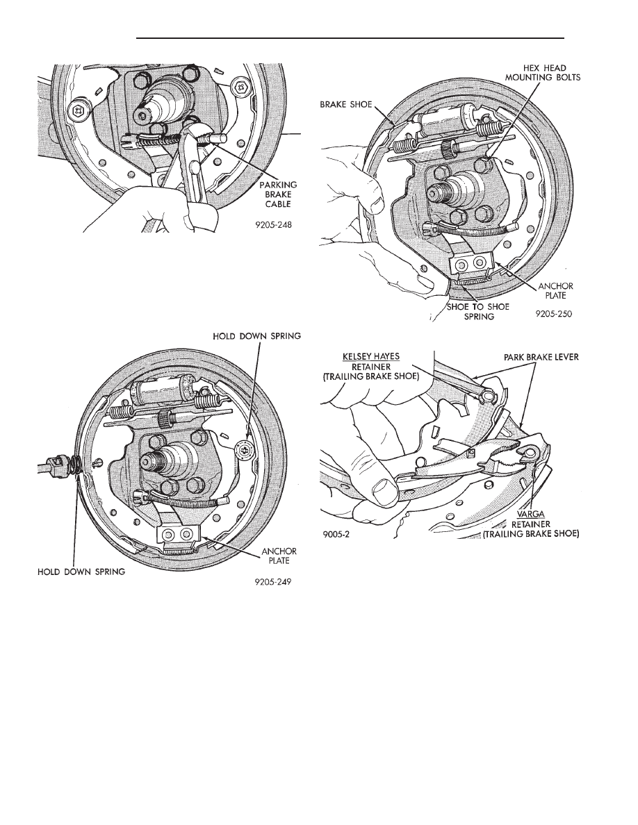
Kelsey Hayes—Leading/trailing shoes; Remove
holddown springs (Fig. 7). Pull assembly down and
away to remove shoes from support plate (Fig. 8). Re-
move brake shoe springs and adjusting screw assem-
bly.
Varga—Leading shoe; Remove the upper shoe to
shoe return spring (Fig. 3). The leading shoe hold
down spring (Fig. 7). And the shoe to shoe spring at
the anchor plate (Fig. 3). Remove shoe and adjuster
assembly.
Varga—Trailing shoe; Remove holddown spring
and lower shoe-to-anchor plate spring.
Kelsey Hayes: Remove park brake lever from
trailing brake shoe by disengaging the retainer clip
(Fig. 9). Be sure not to lose park brake lever wave
washer.
CLEANING AND INSPECTION
Clean metal portion of brake shoes. Check to see if
shoes are bent.
Lining should show contact across entire width and
from heel to toe, otherwise replace.
Shoes with lack of contact at toe or heel maybe im-
properly ground.
Clean and inspect support and adjusting screws.
Apply a thin coat of Mopar Multi-Purpose Lubricant
or equivalent to the threads of the self adjuster (Fig.
10). Replace adjusting screw if corroded.
Fig. 6 Disconnect Parking Brake Cable
Fig. 7 Remove or Install Holddown Springs
Fig. 8 Remove or Install Brake Shoes
Fig. 9 Remove or Install Park Brake Lever Retainer
5 - 20
BRAKES
Ä
Нет комментариевНе стесняйтесь поделиться с нами вашим ценным мнением.
Текст