Chrysler Le Baron, Dodge Dynasty, Plymouth Acclaim. Manual — part 346
(2) Connect sensor wiring lead from harness to
connector on body of sensor.
(3) Install coolant bottle, powertrain control mod-
ule, battery tray and battery.
(4) Install speed control servo to battery tray, if
equipped.
(5) Do not connect negative battery cable. Refer to
Air Bag Systems Check for proper procedure.
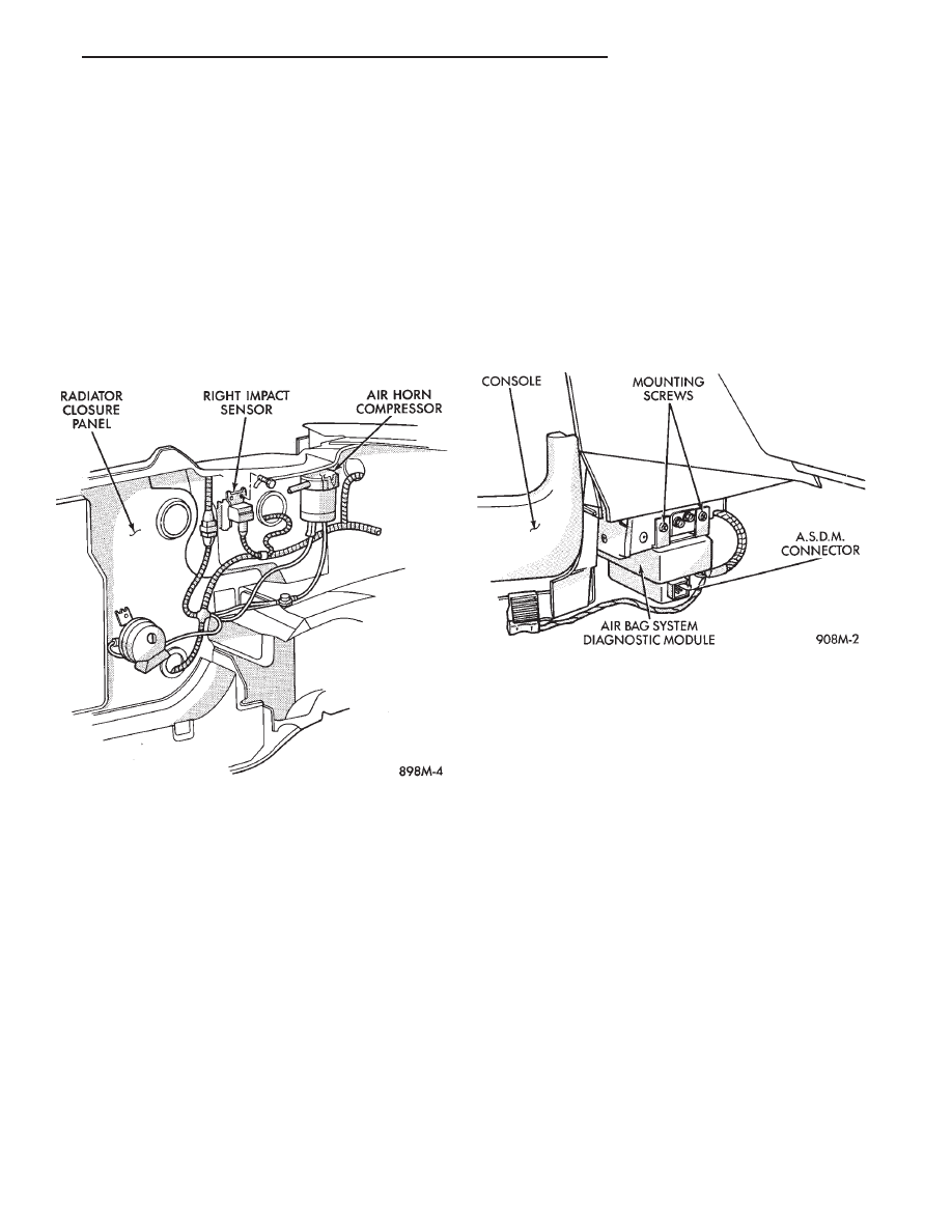
RIGHT FRONT IMPACT SENSOR
REMOVAL
(1) Disconnect battery ground cable and isolate.
(2) Disconnect impact sensor electrical connector
(Fig. 7).
(3) Remove three screws holding sensor to radiator
closure panel. Remove right sensor.
INSTALLATION
(1) Mount right sensor (arrow pointed forward) to
engine side of closure panel using three screws pro-
vided with the new sensor. Tighten 10 to 13 N
Im (90-
120 in. lbs.) torque.
(2) Connect sensor wiring lead from harness to
connector on body of sensor.
(3) Do not connect negative battery cable. Refer to
Air Bag Systems Check for proper procedure.
AIR BAG SYSTEM DIAGNOSTIC MODULE (ASDM)
WARNING: THE ASDM CONTAINS ONE OF THE IM-
PACT SENSORS WHICH ENABLE THE SYSTEM TO
DEPLOY THE AIR BAG. TO AVOID ACCIDENTAL
DEPLOYMENT, NEVER CONNECT ASDM ELECTRI-
CALLY TO THE SYSTEM UNLESS IT IS BOLTED TO
VEHICLE. BEFORE BEGINNING ANY AIR BAG SYS-
TEM REMOVAL OR INSTALLATION PROCEDURES,
REMOVE AND ISOLATE THE BATTERY NEGATIVE
(-) CABLE (GROUND) FROM THE VEHICLE BAT-
TERY. THIS IS THE ONLY SURE WAY TO DISABLE
THE AIR BAG SYSTEM. FAILURE TO DO THIS
COULD RESULT IN ACCIDENTAL AIR BAG DE-
PLOYMENT, AND POSSIBLE PERSONAL INJURY.
REMOVAL
(1) Disconnect battery ground cable, and isolate.
(2) Remove forward console bezel (Fig. 8).
(3) Remove two screws from right side console be-
zel and remove bezel.
(4) Disconnect wiring at ASDM.
(5) Remove module mounting screws, and remove
module.
INSTALLATION
(1) Position the ASDM with the arrow pointing
forward on the console reinforcement. Insert tab on
the ASDM in the slot on the reinforcement.
(2) Attach the ASDM to the support bracket with
the screws supplied and tighten to 1.7 to 2 N
In
(15-20 in. lbs.) torque.
(3) Connect wiring at ASDM, making sure both
connectors are seated and locking tabs engaged.
(4) Install right side console bezel.
(5) Install forward console bezel.
(6) Do not connect negative battery cable. Refer to
Air Bag System Check for proper procedure.
Fig. 7 Right Impact Sensor
Fig. 8 Air Bag System Diagnostic Module (ASDM)
Ä
RESTRAINT SYSTEMS
8M - 5
CLOCKSPRING
WARNING: BEFORE BEGINNING ANY AIR BAG
SYSTEM REMOVAL OR INSTALLATION PROCE-
DURES, REMOVE AND ISOLATE THE BATTERY
NEGATIVE (-) CABLE (GROUND) FROM THE VEHI-
CLE BATTERY. THIS IS THE ONLY SURE WAY TO
DISABLE THE AIR BAG SYSTEM. FAILURE TO DO
SO COULD RESULT IN ACCIDENTAL AIR BAG DE-
PLOYMENT, AND POSSIBLE INJURY.
WHEN AN UNDEPLOYED AIR BAG ASSEMBLY
IS TO BE REMOVED FROM THE STEERING
WHEEL, DISCONNECT BATTERY GROUND CA-
BLE AND ISOLATE. ALLOW SYSTEM CAPACI-
TOR TO DISCHARGE FOR TWO MINUTES, THEN
BEGIN AIR BAG REMOVAL.
REMOVAL
(1) Place the front wheels in the straight ahead po-
sition before starting the repair.
(2) Disconnect battery negative cable and isolate.
(3) Wait two minutes for the reserve capacitor to
discharge before removing undeployed module.
(4) Remove the air bag module.
(5) Remove Speed Control switch and connector if
so equipped or cover.
(6) Disconnect horn terminals.
(7) Remove the steering wheel.
(8) Remove
upper
and
lower
steering
column
shrouds to gain access to clockspring wiring.
(9) Disconnect the 2-way connector between the
clockspring and the instrument panel wiring harness
on top of the fuse block.
(10) To remove, pull clockspring assembly from the
steering column by lifting locating fingers as neces-
sary. The clockspring cannot be repaired, and must
be replaced if faulty.
INSTALLATION
(1) Snap clockspring onto the steering column. If
the clockspring is not properly positioned, follow the
clockspring centering procedure before installing
steering wheel.
(2) Connect the clockspring to the instrument
panel harness, ensure wiring locator clips are prop-
erly seated on wiring trough. Ensure harness locking
tabs are properly engaged.
(3) Install steering column shrouds. Be sure air
bag wire is inside of shrouds.
(4) Front wheels should still be in the straight-
ahead position. Install steering wheel, ensure the
flats on hub align with clockspring. Pull the horn
lead through the smaller upper hole. Pull the air bag
and speed control leads through the larger bottom
hole. Ensure leads are not pinched under the steer-
ing wheel.
(5) Connect the horn lead wire, then the air bag
lead wire to the air bag module.
(6) Install the air bag module and tighten nuts to
9 to 11 N
Im (80 to 100 in. lb.) torque.
(7) Install speed control switch and connector or
cover.
(8) Do not connect battery negative cable. Refer to
Air Bag Systems Check for proper procedure.
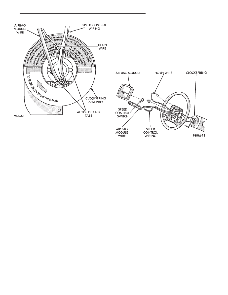
CLOCKSPRING CENTERING PROCEDURE
If the rotating tape within the clockspring is not
positioned properly with the steering wheel and the
front wheels, the clockspring may fail during use.
The following procedure MUST BE USED to center
the clockspring if it is not known to be properly po-
sitioned, or if the front wheels were moved from the
straight ahead position.
WARNING: BEFORE BEGINNING ANY AIR BAG
SYSTEM REMOVAL OR INSTALLATION PROCE-
DURES, REMOVE AND ISOLATE THE BATTERY
NEGATIVE (-) CABLE (GROUND) FROM THE VEHI-
CLE BATTERY. THIS IS THE ONLY SURE WAY TO
DISABLE THE AIR BAG SYSTEM. FAILURE TO DO
THIS COULD RESULT IN ACCIDENTAL AIR BAG
DEPLOYMENT AND POSSIBLE INJURY.
WHEN AN UNDEPLOYED AIR BAG ASSEMBLY
IS TO BE REMOVED FROM THE STEERING
WHEEL, DISCONNECT BATTERY GROUND CA-
BLE AND ISOLATE. ALLOW SYSTEM CAPACI-
TOR TO DISCHARGE FOR TWO MINUTES, THEN
BEGIN AIR BAG REMOVAL.
(1) Place front wheels in the straight ahead posi-
tion.
(2) Wait two minutes for the reserve capacitor to
discharge before removing undeployed module.
(3) Refer to Steering Wheel procedures for removal
of air bag module and steering wheel.
(4) Depress the two plastic locking pins to disen-
gage locking mechanism (Fig. 10).
(5) Keeping locking mechanism disengaged, rotate
the clockspring rotor in the CLOCKWISE DIREC-
TION to the end of travel. Do not apply excessive
torque.
(6) From the end of travel, rotate the rotor two full
turns and a half in the counterclockwise direction.
The horn wire should end up at the top and the squib
wire at the bottom. Engage clockspring locking
mechanism.
(7) Refer to Steering Wheel procedures for installa-
tion of steering wheel and air bag module.
(8) Do not connect battery negative cable. Refer to
Air Bag System Check for proper procedure.
8M - 6
RESTRAINT SYSTEMS
Ä
STEERING WHEEL
WARNING: BEFORE BEGINNING ANY AIR BAG
SYSTEM REMOVAL OR INSTALLATION PROCE-
DURES, REMOVE AND ISOLATE THE BATTERY
NEGATIVE (-) CABLE (GROUND) FROM THE VEHI-
CLE BATTERY. THIS IS THE ONLY SURE WAY TO
DISABLE THE AIR BAG SYSTEM. FAILURE TO DO
THIS COULD RESULT IN ACCIDENTAL AIR BAG
DEPLOYMENT AND POSSIBLE PERSONAL INJURY.
WHEN AN UNDEPLOYED AIR BAG ASSEMBLY
IS TO BE REMOVED FROM THE STEERING
WHEEL, DISCONNECT BATTERY GROUND CA-
BLE AND ISOLATE. ALLOW SYSTEM CAPACI-
TOR
TO
DISCHARGE
FOR
TWO
MINUTES.
BEGIN AIR BAG REMOVAL.
REMOVAL
(1) Make sure front wheels are straight, and steer-
ing column is locked in place.
(2) Disconnect battery negative cable and isolate.
(3) Wait two minutes for the reserve capacitor to
discharge before removing undeployed module.
(4) Remove four nuts attaching air bag module
from the back side of steering wheel.
(5) Lift module, and disconnect connector from rear
of module.
(6) Remove speed control switch and connector if
so equipped or cover.
(7) Remove steering wheel retaining nut.
(8) Remove steering wheel with steering wheel
puller Tool C-3428B.
INSTALLATION
(1) If the clockspring is not properly positioned or
if front wheels were moved, follow the clockspring
centering procedure before installing steering wheel.
With the front wheels in the straight ahead position.
Position the steering wheel on the steering column.
Making sure to fit the flats on the hub of the steer-
ing wheel with the formations on the inside of the
clockspring. Pull the air bag and speed control wires
through the lower, larger hole in the steering wheel
and the horn wire through smaller hole at the top.
Make sure not to pinch wires (Fig. 11).
(2) Install retaining nut, and tighten to 61 N
Im (45
ft. lbs.) torque.
(3) Connect horn wiring lead.
(4) Connect
4-way
connector
to
speed
control
switch and attach switch to steering wheel.
(5) Connect air bag lead wire to air bag module,
and secure module to steering wheel.
(6) Do not connect negative battery cable. Refer to
Air Bag System Check for proper procedure.
STEERING COLUMN SWITCHES
This procedure covers the removal and installation
of the steering wheel and clockspring. Once the
steering wheel and clockspring have been removed,
refer to the appropriate section of this service man-
ual for switch replacement.
WARNING: BEFORE BEGINNING ANY AIR BAG
SYSTEM REMOVAL OR INSTALLATION PROCE-
DURES, REMOVE AND ISOLATE THE BATTERY
NEGATIVE (-) CABLE (GROUND) FROM THE VEHI-
CLE BATTERY. THIS IS THE ONLY SURE WAY TO
DISABLE THE AIR BAG SYSTEM. FAILURE TO DO
THIS COULD RESULT IN ACCIDENTAL AIR BAG
DEPLOYMENT AND POSSIBLE INJURY.
WHEN AN UNDEPLOYED AIR BAG ASSEMBLY
IS TO BE REMOVED FROM THE STEERING
WHEEL, DISCONNECT BATTERY GROUND CA-
BLE AND ISOLATE. ALLOW SYSTEM CAPACI-
Fig. 10 Clockspring (Auto-Locking)
Fig. 11 Steering Wheel Wiring
Ä
RESTRAINT SYSTEMS
8M - 7
TOR
TO
DISCHARGE
FOR
TWO
MINUTES.
BEGIN AIR BAG REMOVAL.
REMOVAL
(1) Disconnect battery negative cable, and isolate.
(2) Wait two minutes for the reserve capacitor to
discharge before removing undeployed module.
(3) Remove four nuts attaching air bag module
from the back side of steering wheel.
(4) Lift module, and disconnect connector from rear
of module.
(5) Remove speed control switch and connector if
so equipped or cover.
(6) Remove steering wheel.
(7) Unsnap clockspring, and remove it.
(8) Refer to the appropriate section for switch re-
placement.
INSTALLATION
(1) Snap clockspring on to steering column. Assure
the 4 way connector is still seated.
(2) Install steering wheel.
(3) Install speed control switch and connector or
cover.
(4) Connect clockspring wiring connector to the
module.
(5) Install four nuts to module, and tighten to 9 to
11 N
Im (80 to 100 in. lbs.) torque.
(6) Do not connect negative battery cable. Refer to
Air Bag System Check for proper procedure.
8M - 8
RESTRAINT SYSTEMS
Ä
Нет комментариевНе стесняйтесь поделиться с нами вашим ценным мнением.
Текст