Chrysler Le Baron, Dodge Dynasty, Plymouth Acclaim. Manual — part 326

(4) Connect a jumper wire between pin 2 of the
four-way servo connector of the main harness and
pin 2 of the vehicle speed control servo (Fig. 12). The
other three pins from the servo should show battery
voltage. If not, replace the servo.
(5) Using an ohmmeter, connect one lead to a good
body ground and the other lead touch pin 1 in the
four-way servo connector of the main harness. The
meter should show continuity. If not, repair the
ground circuit as necessary.
POWERTRAIN CONTROL MODULE ELECTRICAL
TEST
WARNING: ON VEHICLES EQUIPPED WITH AIR-
BAG, SEE GROUP 8M, RESTRAINT SYSTEMS FOR
AIRBAG,
STEERING
WHEEL
OR
COLUMN
RE-
MOVAL PROCEDURES.
(1) Unplug 60-way connector from the powertrain
control module, located next to the battery (Fig. 13).
(2) Remove vehicle speed control switch. Refer to
Vehicle Speed Control Switch Removal. Disconnect
the 4-way connector.
(3) Using an ohmmeter test continuity between pin
23 of powertrain control module and pin 4 of the ve-
hicle speed control switch harness. Refer to Fig. 14
for controller terminal locations.
(a) If no continuity, repair wire circuit as neces-
sary.
(b) Continuity OK, refer to Vehicle Speed Con-
trol Switch Test.
(4) Connect the 4-way connector to vehicle speed
control switch.
(5) Connect negative lead of voltmeter to a good
body ground near the powertrain control module.
(6) Turn ignition switch ON.
(7) Place vehicle speed control switch in the OFF
position. Touch the positive lead of the voltmeter to
pin 53, the voltmeter should read 0 volts.
(8) Place vehicle speed control switch in the ON
position. Touch the positive lead of the voltmeter to
pin 53, the voltmeter should read battery voltage.
(9) If no voltage, repair the wire between pin 53
and pin 3 of the vehicle speed control servo (Fig. 6).
If voltage is OK go to step 8.
(10) Place vehicle speed control switch in the OFF
position. Touch the positive lead of the voltmeter to
pin 33, voltmeter should read 0 volts.
(11) Place vehicle speed control switch in the ON
position. Touch the positive lead of the voltmeter to
pin 33, the voltmeter should read battery voltage.
(12) If no voltage, repair the wire between pin 33
and pin 4 of the vehicle speed control servo (Fig. 6).
If voltage is OK go to step 11.
Fig. 8 Vehicle Speed Control—AC & AY Bodies with 3.3/3.8L
Ä
VEHICLE SPEED CONTROL
8H - 5
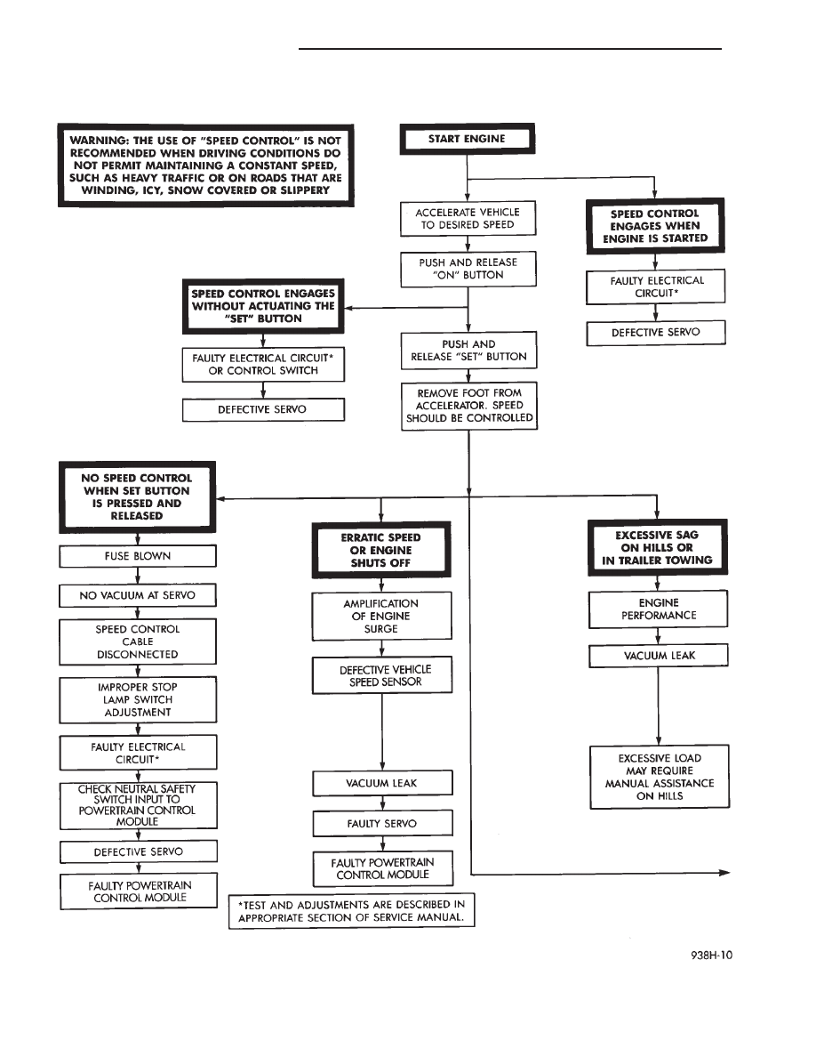
Fig. 9 System Diagnosis
8H - 6
VEHICLE SPEED CONTROL
Ä
(13) Using an ohmmeter, connect one lead to a
good body ground and touch the other lead to pin 29.
When the pedal is depressed, the meter should show
no continuity. With the brake pedal released, the
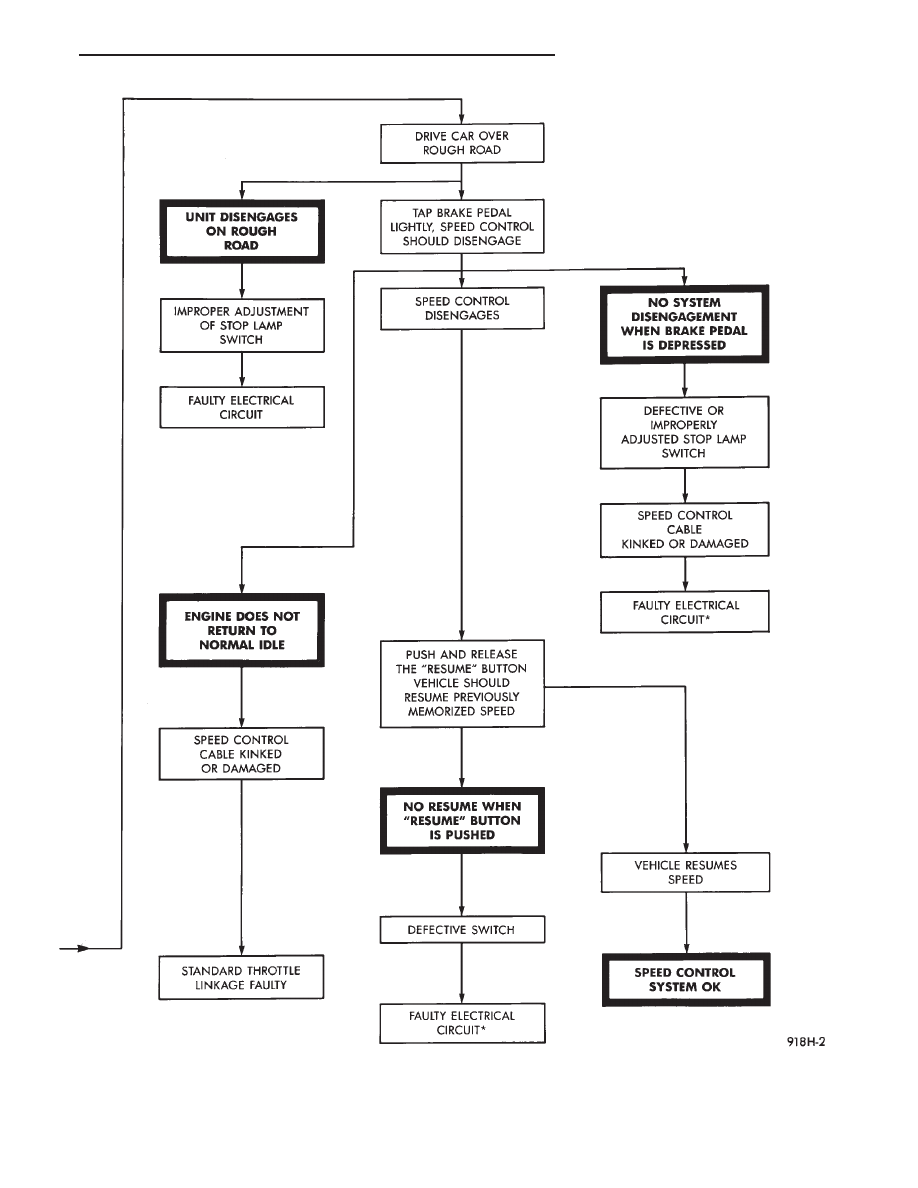
Fig. 10 System Diagnosis—Continued
Ä
VEHICLE SPEED CONTROL
8H - 7
meter should show continuity. If no continuity per-
form the following test. Continuity OK, go to step 12.
(a) Using an ohmmeter test continuity between
pin 29 of powertrain control module and pin 3 of
the stop lamp switch connector.
(b) If no continuity, repair as necessary.
(c) If continuity, refer to Stop Lamp Switch Test.
(d) If stop lamp switch test OK, Test continuity
between pin 6 of stop lamp switch and ground.
(14) Using an ohmmeter, touch one lead to a good
body ground and touch the other lead to pin 30. The
meter should show no continuity when transmission
is in DRIVE and continuity when in PARK or NEU-
TRAL. If not test Neutral Start and Back-Up switch
using DRB II.
VEHICLE SPEED CONTROL SWITCH TEST
WARNING: IF REMOVAL OF AIR BAG MODULE IS
NECESSARY, REFER TO GROUP 8M, RESTRAINT
SYSTEMS.
(1) Remove the switch and disconnect 4-way con-
nector.
(2) Using an ohmmeter, test continuity at the four
pins of the vehicle speed control switch. Refer to Ve-
hicle Speed Control Switch Continuity (Fig. 15).
(3) If there is no continuity or incorrect continuity
at any one of the switch positions, replace the switch.
STOP LAMP VEHICLE SPEED CONTROL SWITCH
TEST
(1) Disconnect the six way connector at the stop
lamp switch (Fig.16). Using an ohmmeter, continuity
may be checked at the switch side of the connector as
follows:
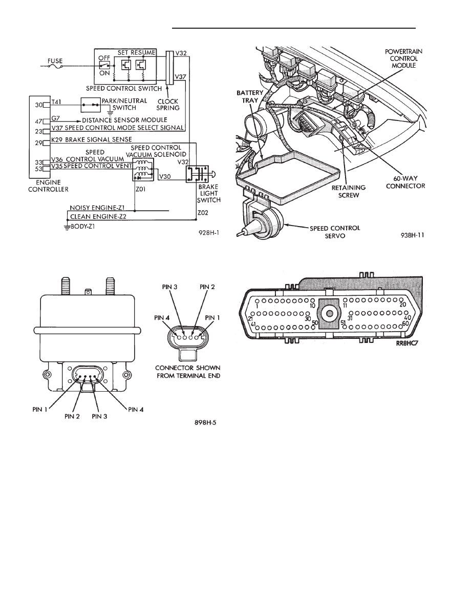
Fig. 11 Vehicle Speed Control Circuit
Fig. 12 Servo Harness Connector
Fig. 13 Powertrain Control Module and Connector
Location
Fig. 14 Powertrain Control Module 60-Way
Connector Shown from Terminal End
8H - 8
VEHICLE SPEED CONTROL
Ä
Нет комментариевНе стесняйтесь поделиться с нами вашим ценным мнением.
Текст