Chrysler Le Baron, Dodge Dynasty, Plymouth Acclaim. Manual — part 59

the PCM determines crankshaft position, it begins
energizing the injectors in sequence.
The auto shutdown (ASD) relay supplies battery
voltage to the injectors. The PCM provides the
ground path for the injectors. By switching the
ground path on and off, the PCM adjusts injector
pulse width. Pulse width is the amount of time the
injector is energized. The PCM adjusts injector pulse
width based on inputs it receives.
IGNITION COIL—PCM OUTPUT
The coil assembly consists of 3 molded coils to-
gether (Fig. 18). The coil assembly is mounted on the
intake manifold. High tension leads route to each
cylinder from the coil. The coil fires two spark plugs
every power stroke. One plug is the cylinder under
compression, the other cylinder fires on the exhaust
stroke. The PCM determines which of the coils to
charge and fire at the correct time.
The auto shutdown (ASD) relay provides battery
voltage to the ignition coil. The PCM provides a
ground contact (circuit) for energizing the coil. When
the PCM breaks the contact, the energy in the coil
primary transfers to the secondary, causing the
spark. The PCM will de-energize the ASD relay if it
does not receive the crankshaft position sensor and
camshaft position sensor inputs. Refer to Auto Shut-
down (ASD) Relay/Fuel Pump Relay—PCM Output
in this section for relay operation.
RADIATOR FAN RELAY—PCM OUTPUT
The radiator fan is energized by the PCM through
the radiator fan relay. The radiator fan relay is lo-
cated on the drivers side fender well near the PCM
(Fig. 14). The PCM grounds the radiator fan relay
when engine coolant reaches a predetermined tem-
perature or the A/C system head pressure is high.
SPEED CONTROL SOLENOIDS—PCM OUTPUT
The speed control vacuum and vent solenoids are
operated by the PCM. When the PCM supplies a
ground to the vacuum and vent solenoids, the speed
control system opens the throttle blade. When the PCM
supplies a ground only to the vent solenoid, the throttle
blade holds position. When the PCM removes the
ground from both the vacuum and vent solenoids, the
throttle blade closes. The PCM balances the two sole-
noids to maintain the set speed. Refer to Group 8H for
speed control information.
TACHOMETER—PCM OUTPUT
The PCM supplies engine RPM to the instrument
panel tachometer through the CCD Bus. The CCD Bus
is a communications port. Various modules use the
CCD Bus to exchange information. Refer to Group 8E
for more information.
MODES OF OPERATION
As input signals to the PCM change, the PCM
adjusts its response to output devices. For example, the
PCM must calculate a different injector pulse width
and ignition timing for idle than it does for wide open
throttle (WOT). There are several different modes of
operation that determine how the PCM responds to the
various input signals.
There are two different areas of operation, Open
Loop and Closed Loop.
During Open Loop modes the PCM receives input
signals and responds according to preset PCM pro-
gramming. Input from the oxygen (O
2
) sensor is not
monitored during Open Loop modes.
During Closed Loop modes the PCM does monitor
the oxygen (O
2
) sensor input. This input indicates to
the PCM whether or not the calculated injector pulse
width results in the ideal air-fuel ratio of 14.7 parts air
to 1 part fuel. By monitoring the exhaust oxygen
content through the O
2
sensor, the PCM can fine tune
the injector pulse width. Fine tuning injector pulse
width allows the PCM to achieve optimum fuel
economy combined with low emissions.
The 3.3L multi-port fuel injection system has the
following modes of operation:
• Ignition switch ON (Zero RPM)
• Engine start-up
• Engine warm-up
• Cruise (Idle)
• Acceleration
• Deceleration
• Wide Open Throttle
• Ignition switch OFF
The engine start-up (crank), engine warm-up, and
wide open throttle modes are OPEN LOOP modes.
Under most operating conditions, the acceleration,
deceleration, and cruise modes, with the engine at
operating temperature are CLOSED LOOP modes.
Fig. 18 Coil Pack—3.3L Engine
Ä
FUEL SYSTEMS
14 - 153
IGNITION SWITCH ON (ZERO RPM) MODE
When the multi-port fuel injection system is acti-
vated by the ignition switch, the following actions oc-
cur:
• The PCM determines atmospheric air pressure
from the MAP sensor input to determine basic fuel
strategy.
• The PCM monitors the coolant temperature sensor
and throttle position sensor input. The PCM modifies
fuel strategy based on this input.
When the key is in the ON position and the engine
is not running (zero rpm), the auto shutdown (ASD)
relay and fuel pump relay are not energized. There-
fore battery voltage is not supplied to the fuel pump,
ignition coil, fuel injectors or oxygen sensor heating
element.
ENGINE START-UP MODE
This is an OPEN LOOP mode. The following ac-
tions occur when the starter motor is engaged.
If the PCM receives the camshaft position sensor
and crankshaft position sensor signals, it energizes
the auto shutdown (ASD) relay and fuel pump relay.
These relays supply battery voltage to the fuel pump,
fuel injectors, ignition coil, and oxygen sensor heat-
ing element. If the PCM does not receive the cam-
shaft position sensor and crankshaft position sensor
signals within approximately one second, it de-ener-
gizes the ASD relay and fuel pump relay.
The PCM energizes all six injectors until it deter-
mines crankshaft position from the camshaft position
sensor and crankshaft position sensor signals. The
PCM determines crankshaft position within 1 engine
revolution.
After determining crankshaft position, the PCM
begins energizing the injectors in sequence. The PCM
adjusts injector pulse width and controls injector syn-
chronization by turning the individual ground paths
to the injectors On and Off.
When the engine idles within
664 RPM of its tar-
get RPM, the PCM compares current MAP sensor
value with the atmospheric pressure value received
during the Ignition Switch On (Zero RPM) mode. If
the PCM does not detect a minimum difference be-
tween the two values, it sets a MAP fault into mem-
ory.
Once the ASD and fuel pump relays have been en-
ergized, the PCM:
• Determines injector pulse width based on battery
voltage, coolant temperature, engine rpm and the
number of engine revolutions since cranking was ini-
tiated.
ENGINE WARM-UP MODE
This is a OPEN LOOP mode. The following inputs
are received by the PCM:
• engine coolant temperature
• manifold absolute pressure (MAP)
• engine speed (crankshaft position sensor)
• throttle position
• A/C switch
• battery voltage
The PCM adjusts injector pulse width and controls
injector synchronization by turning the individual
ground paths to the injectors On and Off.
The PCM adjusts ignition timing and engine idle
speed. Engine idle speed is adjusted through the idle
air control motor.
CRUISE OR IDLE MODE
When the engine is at operating temperature this
is a CLOSED LOOP mode. During cruising speed the
following inputs are received by the PCM:
• engine coolant temperature
• manifold absolute pressure
• engine speed (crankshaft position sensor)
• throttle position
• exhaust gas oxygen content
• A/C control positions
• battery voltage
The PCM adjusts injector pulse width and controls
injector synchronization by turning the individual
ground paths to the injectors On and Off.
The PCM adjusts engine idle speed and ignition
timing. The PCM adjusts the air/fuel ratio according
to the oxygen content in the exhaust gas.
ACCELERATION MODE
This is a CLOSED LOOP mode. The PCM recog-
nizes an abrupt increase in throttle position or MAP
pressure as a demand for increased engine output
and vehicle acceleration. The PCM increases injector
pulse width in response to increased fuel demand.
DECELERATION MODE
This is a CLOSED LOOP mode. During decelera-
tion the following inputs are received by the PCM:
• engine coolant temperature
• manifold absolute pressure
• engine speed
• throttle position
• exhaust gas oxygen content
• A/C control positions
• battery voltage
The PCM may receive a closed throttle input from
the throttle position sensor (TPS) when it senses an
abrupt decrease in manifold pressure. This indicates
a hard deceleration. The PCM will reduce injector
pulse width. This helps maintain better control of the
air-fuel mixture (as sensed through the O
2
sensor).
During a closed throttle deceleration condition, the
PCM grounds the exhaust gas recirculation (EGR)
solenoid. When the solenoid is grounded, EGR func-
tion stops.
14 - 154
FUEL SYSTEMS
Ä
WIDE OPEN THROTTLE MODE
This is an OPEN LOOP mode. During wide-open-
throttle operation, the following inputs are received
by the PCM:
• battery voltage
• engine coolant temperature
• manifold absolute pressure
• engine speed
• throttle position
When the PCM senses wide open throttle condition
through the throttle position sensor (TPS) it will:
• De-energize the air conditioning relay. This dis-
ables the air conditioning system.
• Provide a ground for the electrical EGR transducer
(EET) solenoid. When the PCM grounds the solenoid,
the EGR system stops operating.
The exhaust gas oxygen content input is not ac-
cepted by the PCM during wide open throttle opera-
tion. The PCM will adjust injector pulse width to
supply a predetermined amount of additional fuel.
IGNITION SWITCH OFF MODE
When the ignition switch is turned to the OFF po-
sition, the following occurs:
• All outputs are turned off.
• No inputs are monitored.
• The PCM shuts down.
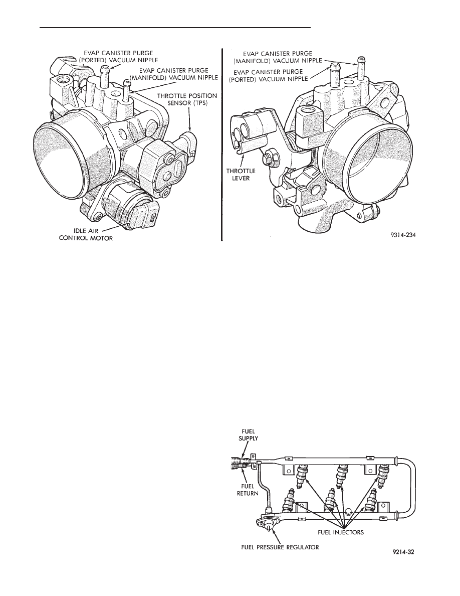
THROTTLE BODY
The throttle body assembly is located on the left
side of the intake manifold plenum (Fig. 19). The
throttle body houses the throttle position sensor and
the idle air control motor. Air flow through the throt-
tle body is controlled by a cable operated throttle
blade located in the base of the throttle body.
FUEL SUPPLY CIRCUIT
Fuel is pumped to the fuel rail by an electrical
pump in the fuel tank. The pump inlet is fitted with
a strainer to prevent water and other contaminants
from entering the fuel supply circuit.
Fuel pressure is controlled to a preset level above
intake manifold pressure by a pressure regulator.
The regulator is mounted on the fuel rail. The regu-
lator uses intake manifold pressure as a reference.
FUEL INJECTORS AND FUEL RAIL ASSEMBLY
Six fuel injectors are retained in the fuel rail by
lock rings (Fig. 20). The rail and injector assembly is
installed in position with the injectors inserted in re-
cessed holes in the intake manifold.
Fig. 19 Throttle Body
Fig. 20 Fuel Rail Assembly
Ä
FUEL SYSTEMS
14 - 155
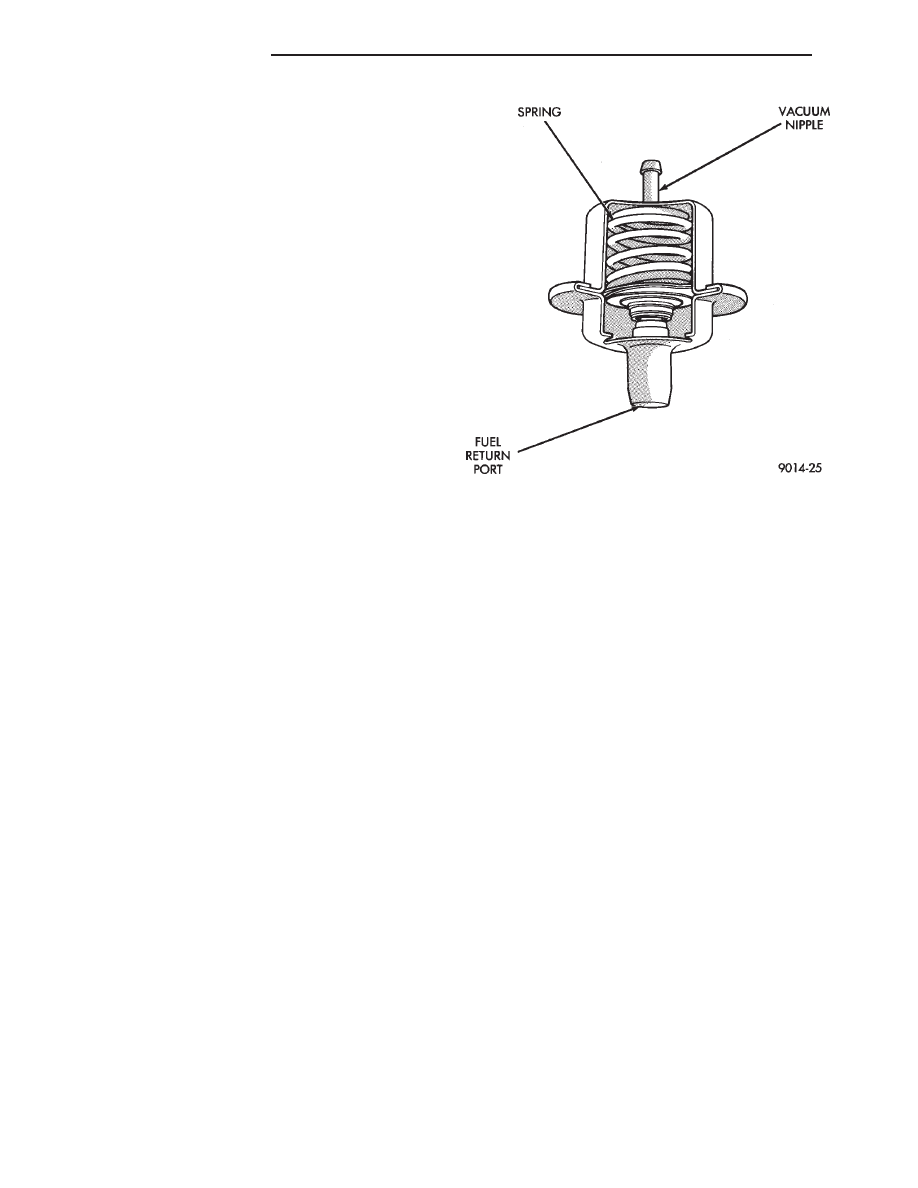
FUEL PRESSURE REGULATOR
The pressure regulator is a mechanical device lo-
cated on the fuel rail, downstream of the fuel injec-
tors (Fig. 21). The regulator maintains a constant
330 kPa (48 psi) across the fuel injector tip.
The regulator contains a spring loaded rubber dia-
phragm that covers the fuel return port. When the
fuel pump is operating, fuel flows past the injectors
into the regulator, and is restricted from flowing any
further by the blocked return port. When fuel pres-
sure reaches 330 kPa (48 psi) it pushes on the dia-
phragm, compresses the spring, and uncovers the
fuel return port. The diaphragm and spring con-
stantly move from an open to closed position keeping
fuel pressure consistent.
Fig. 21 Fuel Pressure Regulator
14 - 156
FUEL SYSTEMS
Ä
Нет комментариевНе стесняйтесь поделиться с нами вашим ценным мнением.
Текст