Chrysler Le Baron, Dodge Dynasty, Plymouth Acclaim. Manual — part 225

BRAKE DISC (ROTOR)
INDEX
page
page
Braking Disc Removal
. . . . . . . . . . . . . . . . . . . . . 54
General Information
. . . . . . . . . . . . . . . . . . . . . . . 53
Inspection Diagnosis
. . . . . . . . . . . . . . . . . . . . . . 53
Installing Braking Disc
. . . . . . . . . . . . . . . . . . . . . 54
Refinishing Braking Disc
. . . . . . . . . . . . . . . . . . . 55
Service Procedures
. . . . . . . . . . . . . . . . . . . . . . . 53
GENERAL INFORMATION
Any servicing of the braking disc requires extreme
care to maintain the braking disc within service toler-
ances to ensure proper brake action.
CAUTION: If the braking disk (rotor) needs to be
replaced with a new part. The protective coating on
the braking surfaces of the rotor MUST BE REMOVED
with an appropriate solvent, to avoid contamination
of the brake shoe linings.
When replacing a rotor with a new part do NOT
reface the new rotor. Rotor already has the re-
quired micro finish when manufactured, only
remove the protective coating.
INSPECTION DIAGNOSIS
Before refinishing or refacing a braking disc, the disc
should be checked and inspected for the following
conditions:
Braking surface scoring, rust, impregnation of lining
material and worn ridges.
Excessive lateral rotor runout or wobble.
Thickness variation (Parallelism).
Dishing or distortion (Flatness).
If a vehicle has not been driven for a period of time.
The discs will rust in the area not covered by the brake
lining and cause noise and chatter when the brakes are
applied.
Excessive wear and scoring of the disc can cause
temporary improper lining contact if ridges are not
removed before installation of new brake shoe assem-
blies.
Some discoloration or wear of the disc surface is
normal and does not require resurfacing when linings
are replaced.
Excessive runout or wobble in a disc can increase
pedal travel due to piston knock back. This will in-
crease guide pin bushing wear due to tendency of
caliper to follow disc wobble.
Thickness variation in a disc can also result in pedal
pulsation, chatter and surge due to variation in brake
output. This can also be caused by excessive runout in
braking disc or hub.
Dishing or distortion can be caused by extreme heat
and abuse of the brakes.
SERVICE PROCEDURES
CHECKING BRAKING DISC FOR RUNOUT AND
THICKNESS
On vehicle, braking disc (rotor) runout is the com-
bination of the individual runout of the hub face and
the runout of the disc. (The hub and disc are separa-
ble). To measure runout on the vehicle, remove the
wheel and reinstall the lug nuts tightening the disc
to the hub. Mount Dial Indicator, Special Tool
C-3339 with Mounting Adaptor, Special Tool SP-1910
on steering arm. Dial indicator plunger should con-
tact disc (braking surface) approximately one inch
from edge of disc (See Fig. 1). Check lateral runout
(both sides of disc) runout should not exceed 0.13 mm
(0.005 inch).
If runout is in excess of the specification, check the
lateral runout of the hub face. Before removing disc
from hub, make a chalk mark across both the disc
and one wheel stud on the high side of runout. So
you’ll know exactly how the disc and hub was origi-
nally mounted (Fig. 2). Remove disc from hub.
Install Dial Indicator, Special Tool C-3339 and
Mounting Adaptor, Special Tool SP-1910 on steering
Fig. 1 Checking Braking Disc for Runout
Ä
BRAKES
5 - 53

knuckle. Position stem so it contacts hub face near
outer diameter. Care must be taken to position stem
outside the stud circle but inside the chamfer on the
hub rim. Clean hub surface before checking. (See
Fig. 3)
Runout should not exceed 0.08 mm (0.003 inch). If
runout exceeds this specification, hub must be re-
placed. See Suspension Group 2. If hub runout does
not exceed this specification, install disc on hub with
chalk marks two wheel studs apart (Fig. 4). Tighten
nuts in the proper sequence and torque to specifica-
tions. Finally, check runout of disc to see if runout is
now within specifications.
If runout is not within specifications. Install a new
braking disc or reface disc, being careful to remove
as little as possible from each side of disc. Remove
equal amounts from each side of disc. Do not reduce
thickness below minimum thickness cast into the un-
machined surface of the rotor.
Thickness variation measurements of disc should
be made in conjunction with runout. Measure thick-
ness of disc at 12 equal points with a micrometer at
a radius approximately 25.4 mm (1 inch) from edge
of disc (Fig. 5). If thickness measurements vary by
more than 0.013 mm (0.0005 inch) disc should be re-
moved and resurfaced (Figs. 6 and 7), or a new disc
installed. If cracks or burned spots are evident in the
disc, disc must be replaced.
Light scoring and/or wear is acceptable. If heavy
scoring or warping is evident, the disc must be refin-
ished or replaced (See Refinishing/Refacing Braking
Disc). If cracks are evident in the disc, replace the
disc.
BRAKING DISC REMOVAL
(1) Raise vehicle on hoist or jackstands. Remove
wheel and tire assembly.
(2) Remove caliper assembly, as described under
Brake Shoe Removal in this Group, (but do not dis-
connect brake line). Suspend caliper from wire hook
or loop to avoid strain on flexible hose.
(3) Remove braking disc from the hub.
INSTALLING BRAKING DISC
(1) Slide braking disc on hub. Clean both sides of
braking disc with alcohol or suitable solvent.
(2) Install caliper assembly, as described in Brake
Shoe Installation paragraph.
Fig. 2 Marking Braking Disc and Wheel Stud
Fig. 3 Checking Hub for Runout
Fig. 4 Index Braking Disc and Wheel Stud
5 - 54
BRAKES
Ä

REFINISHING BRAKING DISC
REFACING BRAKING DISC
Refacing of the braking disc is not required each
time the shoe assemblies are replaced.
If the braking disc surface is deeply scored or
warped or there is a complaint of brake roughness or
pulsation the rotor should be resurfaced or refaced
(Figs. 6 and 7).
When refacing a braking disc the required 0.10
mm (0.004 inch) TIR (Total Indicator Reading) and
0.013 mm (0.0005 inch) thickness variation limits
MUST BE MAINTAINED. Extreme care in the op-
eration of braking disc turning equipment is re-
quired.
The collets, shafts and adapters used on the brake
lathe and the bearing cups in the rotor MUST be
clean and free from any chips or contamination.
When mounting the disc on the brake lathe, strict
attention to the brake lathe manufacturer’s operat-
ing instructions is required.
If the disc is not mounted properly the run-out will
be worse after refacing than before refacing.
The use of a double straddle cutter (Fig. 6) that
machines both sides of the disc at the same time is
highly recommended.
RESURFACING BRAKING DISC
This operation can be used when disc surface is
rusty, has lining deposits or excessive runout or
thickness variation is evident.
A sanding disc attachment will remove surface con-
tamination without removing much braking disc ma-
terial.
It will generally follow variations in thickness that
are in the disc.
The following chart shows the location of measure-
ments and specifications when servicing the braking
disc.
All braking discs have markings for minimum
allowable thickness cast on an un-machined sur-
face of the braking disc (Fig. 8). The thickness
Fig. 5 Checking Disc for Thickness
Fig. 6 Refacing Braking Disc
Fig. 7 Resurfacing Braking Disc (Final Finish)
Ä
BRAKES
5 - 55
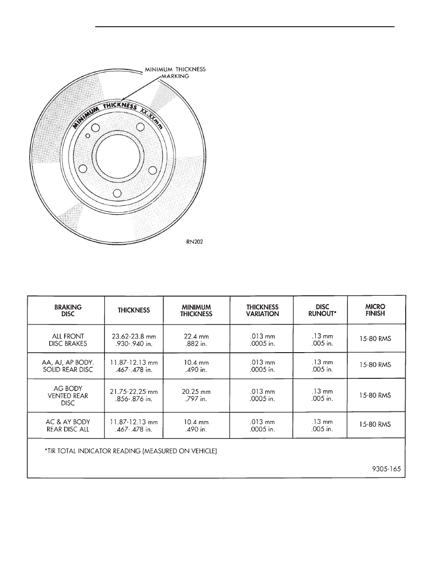
markings may be located on the disc as shown
in (Fig. 8) or on an alternate surface.
This marking includes 0.76 mm (0.030 inch) allow-
able
disc
wear
beyond
the
recommended
0.76
mm(0.030 inch) of disc refacing.
Fig. 8 Minimum Thickness Markings
BRAKING DISC (ROTOR) REFINISHING LIMITS
5 - 56
BRAKES
Ä
Нет комментариевНе стесняйтесь поделиться с нами вашим ценным мнением.
Текст