Chrysler Le Baron, Dodge Dynasty, Plymouth Acclaim. Manual — part 295

(2) With engine running, move test probe along
entire length of all cables (approximately 0 to 1/8
inch gap). If punctures or cracks are present there
will be a noticeable spark jump from the faulty area
to the probe. Cracked, leaking or faulty cables should
be replaced.
Use the following procedure when removing the
high tension cable from the spark plug. First, remove
the cable from the retaining bracket. Then grasp the
terminal as close as possible to the spark plug. Ro-
tate the cover (boot) slightly and pull straight back.
Do not use pliers and do not pull the cable at an
angle. Doing so will damage the insulation, cable
terminal or the spark plug insulator. Wipe spark
plug insulator clean before reinstalling cable
and cover.
Resistance cables are identified by the words Elec-
tronic Suppression.
Use an ohmmeter to check cables for opens, loose
terminals or high resistance.
(a) Remove cable from spark plug.
(b) Remove cable from the coil tower.
(c) Connect the ohmmeter between spark plug
end terminal and the coil end terminal. Resistance
should be within tolerance shown in the cable re-
sistance chart. If resistance is not within tolerance,
replace cable assembly. Test all spark plug cables
in same manner.
SPARK PLUG SERVICE
When replacing the spark plug cables, route the ca-
bles correctly and secure them in the appropriate re-
tainers. Incorrectly routed cables can cause the radio
to reproduce ignition noise. It can also cause cross ig-
nition of the spark plugs or short circuit the cables to
ground.
SPARK PLUG REMOVAL
Always remove cables by grasping at boot, rotating
the boot 1/2 turn, and pulling straight back in a
steady motion.
(1) Prior to removing the spark plug spray com-
pressed air around the spark plug hole and the area
around the spark plug.
(2) Remove the spark plug using a quality socket
with a rubber or foam insert.
(3) Inspect the spark plug condition. Refer to
Spark Plug Condition in this section.
SPARK PLUG GAP ADJUSTMENT
Check the spark plug gap with a gap gauge. If the
gap is not correct, adjust it by bending the ground
electrode (Fig. 6).
SPARK PLUG INSTALLATION
(1) To avoid cross threading, start the spark plug
into the cylinder head by hand.
(2) Tighten spark plugs to 28 N
Im (20 ft. lbs.)
torque.
(3) Install spark plug cables over spark plugs.
IDLE RPM TEST
WARNING: BE SURE TO APPLY PARKING BRAKE
AND/OR BLOCK WHEELS BEFORE PERFORMING
ANY ENGINE RUNNING TESTS.
Engine idle set rpm should be tested and recorded
as it is when the vehicle is first brought into shop
for testing. This will assist in diagnosing complaints
of engine stalling, creeping and hard shifting on ve-
hicles equipped with automatic transaxle. Refer to the
Throttle Body Minimum Airflow procedures in Group
14.
IGNITION TIMING PROCEDURE
Ignition timing cannot be changed or set on Turbo
III, 3.3L or 3.8L engines. For diagnostic information,
refer to the DRBII scan tool and the appropriate
Powertrain Diagnostics Procedures manual.
CABLE RESISTANCE CHART
Fig. 6 Setting Spark Plug Gap—Typical
Ä
IGNITION SYSTEMS
8D - 41
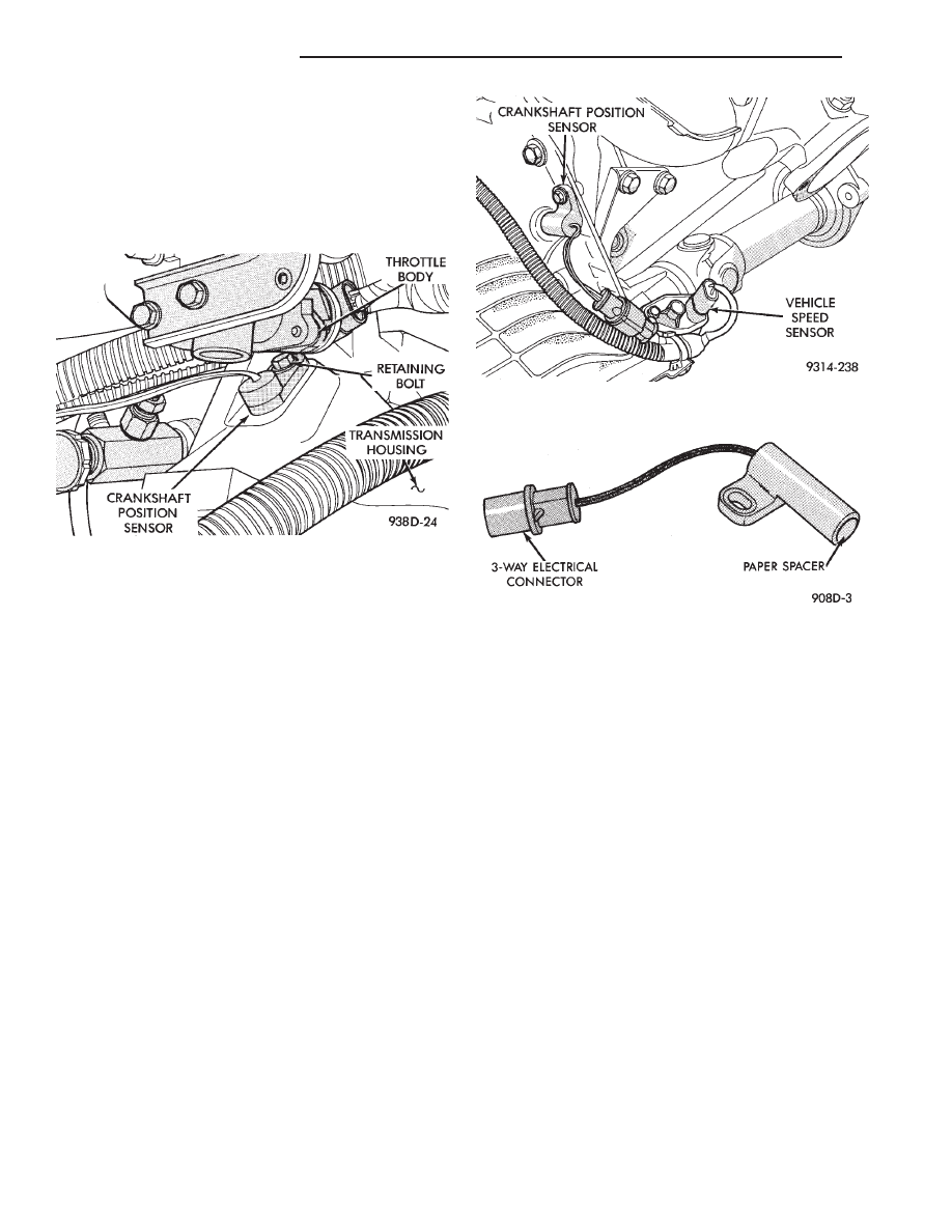
CRANKSHAFT POSITION SENSOR—TURBO III EN-
GINE
REMOVAL
(1) Remove throttle body.
(2) Remove inter-cooler to turbo-charger air hose.
(3) Disconnect crank timing sensor pick-up lead at
wiring harness connector (Fig. 7).
(4) Remove crank timing sensor retaining bolt.
(5) Pull crank timing sensor straight up out of the
transaxle housing.
INSTALLATION
(1) Install sensor in transaxle. Push sensor down
until contact is made with the transaxle housing. Hold
the sensor in this position. Install and tighten retain-
ing bolt to 16 N
Im (145 in. lbs.) torque.
(2) Connect electrical connector to sensor.
CRANKSHAFT POSITION SENSOR—3.3L AND 3.8L
ENGINES
REMOVAL
(1) Disconnect crankshaft position sensor electrical
connector from the wiring harness connector (Fig. 8).
(2) Remove sensor retaining bolt.
(3) Pull crankshaft position sensor straight up out of
the transaxle housing.
INSTALLATION
If installing the original sensor, clean off the
old spacer on the sensor face. A NEW SPACER
must be attached to the sensor face before instal-
lation. If the sensor is being replaced, confirm
that the paper spacer is attached to the face of
the new sensor (Fig. 9).
(1) Install sensor in transaxle and push sensor down
until contact is made with the drive plate. While
holding the sensor in this position, and install and
tighten the retaining bolt to 12 N
Im (105 in. lbs.)
torque.
(2) Connect crankshaft position sensor electrical
connector to the wiring harness connector.
CAMSHAFT POSITION SENSOR SERVICE—TURBO
III ENGINE
REMOVAL
(1) Disconnect camshaft position sensor connector
from wiring harness (Fig. 10).
(2) Remove camshaft position sensor retaining bolt
and remove sensor.
INSTALLATION
If installing the original sensor, clean off the
old spacer on the sensor face. A NEW SPACER
must be attached to the face before installation.
If the sensor is being replaced, confirm that the paper
spacer is attached to the face (Fig. 11).
(1) Install sensor in the cylinder head and push
sensor down until contact is made with the camshaft
gear. While holding the sensor in this position, install
and tighten the retaining bolt 16 N
Im (145 in. lbs.)
torque.
(2) Connect electrical connector to the sensor.
Fig. 7 Crankshaft Position Sensor Service—Turbo III
Engine
Fig. 8 Crankshaft Position Sensor—3.3L and 3.8L
Engines
Fig. 9 Crankshaft Position Sensor and Spacer
8D - 42
IGNITION SYSTEMS
Ä
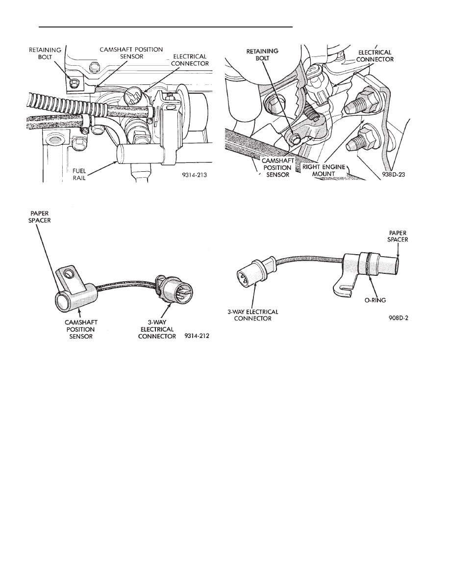
CAMSHAFT POSITION SENSOR—3.3L AND 3.8L
ENGINES
REMOVAL
(1) Disconnect camshaft position sensor electrical
connector from the wiring harness (Fig. 12).
(2) Remove engine mount support bracket.
(3) Loosen camshaft position sensor retaining bolt
enough to allow slot in sensor to slide past the bolt.
(4) Pull sensor up out of the chain case cover. Do not
pull on the sensor lead. There is an O-ring on the
sensor case. The O-ring may make removal difficult. A
light tap to top of sensor prior to removal may reduce
force needed for removal.
INSTALLATION
If installing the original sensor, clean off the
old spacer on the sensor face. A NEW SPACER
must be attached to the face before installation.
Inspect O-ring for damage, replace if necessary. If the
sensor is being replaced, confirm that the paper
spacer is attached to the face and O-ring is posi-
tioned in groove of the new sensor (Fig. 13).
(1) Apply a couple drops of clean engine oil to the
O-ring prior to installation. Install sensor in the
chain case cover and push sensor down until contact
is made with the camshaft timing gear. While hold-
ing the sensor in this position, install and tighten
the retaining bolt 14 N
Im (125 in. lbs.) torque.
(2) Connect camshaft position sensor electrical con-
nector to harness connector. Position connector away
from the accessory belt.
(3) Install engine mount support bracket.
IGNITION COIL SERVICE—TURBO III ENGINE
(1) Remove spark plug cables from coil (Fig. 14).
(2) Remove electrical connector from coil pack.
(3) Remove ignition coil fasteners.
(4) Reverse the above procedure for installation.
Tighten fasteners to 12 N
Im (105 in. lbs.) torque.
IGNITION COIL—3.3L AND 3.8L ENGINE
(1) Remove spark plug cables from coil (Fig. 15).
(2) Remove ignition coil electrical connector.
(3) Remove ignition coil mounting screws.
(4) Remove ignition coil.
Fig. 12 Camshaft Position Sensor Location—3.3L
and 3.8L Engine
Fig. 13 Camshaft Position Sensor—3.3L and 3.8L
Engines
Fig. 10 Camshaft Position Sensor Location—Turbo
III Engines
Fig. 11 Camshaft Position Sensor—Turbo III Engine
Ä
IGNITION SYSTEMS
8D - 43

Reverse
the
above
procedure
for
installation.
Tighten mounting screws to 12 N
Im (105 in. lbs.)
torque.
MANIFOLD ABSOLUTE PRESSURE (MAP)
SENSOR—TURBO III ENGINE
The map sensor mounts to the right front fender
(Fig. 16).
(1) Remove vacuum hose from MAP sensor.
(2) Remove MAP sensor mounting screws.
(3) Remove electrical connector from sensor.
(4) Reverse procedure for installation.
MANIFOLD ABSOLUTE PRESSURE (MAP)
SENSOR—3.3L AND 3.8L ENGINES
The alignment of the MAP sensor is critical to the
sensors performance. The top of the sensor is marked
This Side Up (Fig. 17).
(1) Disconnect electrical connector from MAP sen-
sor.
(2) Remove sensor by unscrewing from the intake
manifold (Fig. 17).
(3) Reverse the above procedure for installation.
Fig. 14 Ignition Coil Service—2.2L Turbo III
Fig. 15 Ignition Coil Removal and Installation
Fig. 16 MAP Sensor—Turbo III Engine
Fig. 17 Manifold Absolute Pressure Sensor
8D - 44
IGNITION SYSTEMS
Ä
Нет комментариевНе стесняйтесь поделиться с нами вашим ценным мнением.
Текст