Chrysler Le Baron, Dodge Dynasty, Plymouth Acclaim. Manual — part 11

(2) Beginning at the ball joint, align and torque
shoulder bolts (Fig. 3).
(3) Working from the front of system, align and
clamp each component to maintain position and
proper clearance with underbody parts (Fig. 10).
(4) Tighten all clamps and supports to the proper
torques and clearances.
INTAKE AND EXHAUST MANIFOLDS—TBI ENGINE
INTAKE MANIFOLD
Naturally Aspirated Die-cast aluminum long-
branch fan design with remote plenum. The throttle
body is installed on the upper plenum of the mani-
fold.
EXHAUST MANIFOLD
All high strength iron casting that intermesh with
the intake manifold. For standard engines a four
branch design collects and directs exhaust gases to
the conical (articulated joint connection) outlet.
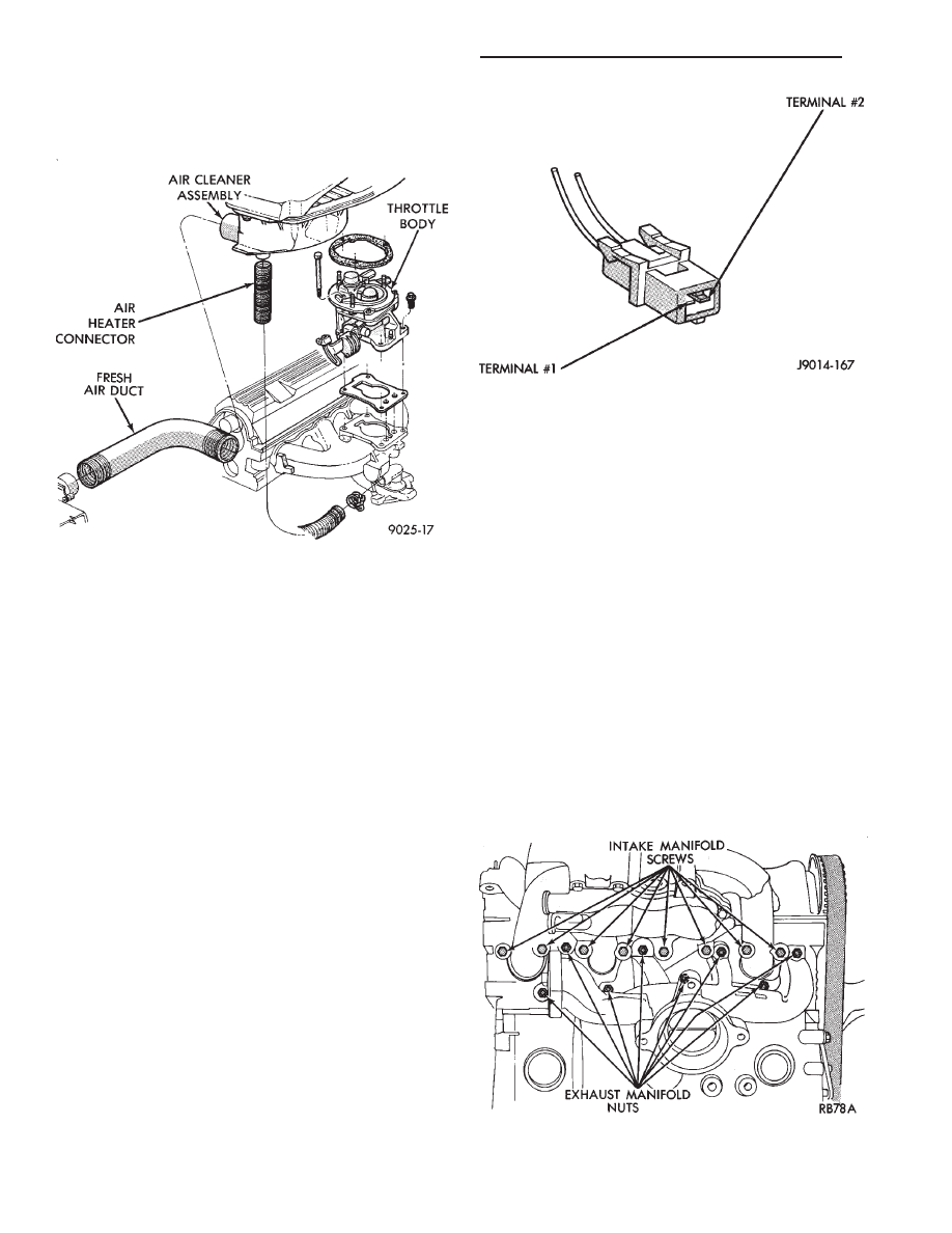
THROTTLE BODY AIR HEATER
The throttle body air heater (Fig. 1) is attached to
the exhaust manifold and is removable.
Inspect air heater connector tube; replace if dam-
aged. Refer to Emission Control Systems Group 25,
Fig. 9 First Slip Joint Connection
Fig. 10 Exhaust Clearance
Fig. 8 Front Tail Pipe Uni-Clamp
Ä
EXHAUST SYSTEM AND INTAKE MANIFOLD
11 - 5
for diagnostic and service procedures on the air control
valve and temperature sensor located in the air
cleaner.
INTAKE AND EXHAUST MANIFOLDS SERVICE—TBI
ENGINE
Intake and exhaust manifolds use a one piece gasket.
Service procedures requiring removal and installation
( of either ) must include both manifolds.
FUEL SYSTEM PRESSURE RELEASE PROCE-
DURE
The Fuel System is under a constant pressure
of at least 265 kPa (39 psi). Before servicing the
fuel pump, fuel lines, fuel filter, throttle body or
fuel injector, the fuel system pressure must be
released.
(a) Loosen fuel filler cap to release fuel tank pres-
sure.
(b) Disconnect injector wiring harness from engine
harness.
(c) Connect a jumper wire to ground terminal
Number 1 of the injector harness (Fig. 2) to engine
ground.
(d) Connect a jumper wire to the positive terminal
Number 2 of the injector harness (Fig. 2) and touch
the battery positive post for no longer than 5 seconds.
This releases system pressure.
(e) Remove jumper wires.
(f) Continue fuel system service.
REMOVAL
(1) Perform fuel system pressure release procedure
before attempting any repairs.
(2) Disconnect negative battery cable. Drain cool-
ing system. Refer to Cooling System, Group 7 for pro-
cedure.
(3) Remove air cleaner and disconnect all vacuum
lines, electrical wiring and fuel lines from throttle
body.
(4) Remove throttle linkage.
(5) Loosen power steering pump and remove belt.
(6) Remove power brake vacuum hose from intake
manifold.
(7) Disconnect EGR tube from intake manifold and
remove water hoses from water crossover.
(8) Raise vehicle and remove exhaust pipe from
manifold.
(9) Remove power steering pump assembly and set
aside.
(10) Remove
intake
manifold
retaining
screws
(Fig. 3).
(11) Lower vehicle and remove intake manifold.
(12) Remove exhaust manifold retaining nuts (Fig.
3).
(13) Remove exhaust manifold.
Fig. 2 Injector Harness Connector
Fig. 3 Intake and Exhaust Manifold Attaching
Points—2.2/2.5L Engines
Fig. 1 Air Heater—TBI Engine
11 - 6
EXHAUST SYSTEM AND INTAKE MANIFOLD
Ä

CLEANING AND INSPECTION
(1) Discard gaskets and clean all gasket surfaces
on both manifolds and on cylinder head.
(2) Test gasket surfaces of manifolds for flatness
with a straight edge. Surfaces must be flat within
0.15mm per 300mm (.006 in. per foot) of manifold
length.
(3) Inspect manifolds for cracks and distortion.
INSTALLATION
(1) Install a new intake and exhaust manifold gas-
ket. Coat steel gasket lightly with Gasket Sealer on
manifold side. Do not coat composition gasket with
(any) sealer.
(2) Set exhaust manifold in place. Tighten retain-
ing nuts starting at center and progressing outward
in both directions to 23 N
Im (200 in. lbs.) torque. Re-
peat this procedure until all nuts are at specified
torque.
(3) Set intake manifold in place.
(4) Raise vehicle and tighten retaining screws
starting at center and progressing outward in both
directions to 23 N
Im (200 in. lbs.) torque (Fig. 3). Re-
peat this procedure until all screws are at specified
torque.
(5) Reverse removal procedures 1-9 for installation.
(6) With the DRBII Scan Tool use ASD Fuel Sys-
tem Test to pressurize system to check for leaks.
CAUTION: When using the ASD Fuel System Test,
the Auto Shutdown (ASD) relay will remain ener-
gized for 7 minutes or until the ignition switch is
turned to the OFF position, or Stop All Test is se-
lected.
INTAKE AND EXHAUST MANIFOLDS—FLEXIBLE
FUEL ENGINE
INTAKE MANIFOLD
The manifold is die-cast aluminum with upper ple-
num and 4 tubes lower runners. These attach to the
cylinder head, with each runner leading directly to a
cylinder.
The manifold is also machined for fuel rail attach-
ment and injector installation. The throttle body is
installed on the upper plenum of the manifold.
EXHAUST MANIFOLD
All high strength iron casting that intermesh with
the intake manifold. For standard engines a four
branch design collects and directs exhaust gases to
the conical (articulated joint connection) outlet.
INTAKE/EXHAUST MANIFOLDS
SERVICE—FLEXIBLE FUEL ENGINES
Intake and exhaust manifolds use a one piece gas-
ket. Service procedures requiring removal and instal-
lation of either must include both manifolds.
SERVICE PRECAUTIONS
Methanol is more toxic than gasoline. Always re-
lease fuel system pressure before servicing fuel sys-
tem components and wear methanol resistant gloves
and eye protection.
Avoid breathing methanol vapors or ingesting
methanol. Headaches, dizziness and even uncon-
sciousness could result from breathing these vapors.
Serious injury, blindness and even death could result
from ingesting methanol.
Methanol vapors are extremely flammable and can
travel along the ground. Service vehicles in well ven-
tilated areas and avoid ignition sources. Never
smoke while servicing the vehicle.
Do not allow methanol to contact skin. Prolonged
contact with methanol can cause dry skin or an al-
lergic skin reaction. Also, prolonged contact could re-
sult in absorption through the skin.
FUEL SYSTEM PRESSURE RELEASE
PROCEDURE
WARNING: RELEASE FUEL SYSTEM PRESSURE
BEFORE SERVICING FUEL SYSTEM COMPONENTS.
WEAR METHANOL RESISTANT GLOVES AND EYE
PROTECTION WHILE SERVICING THE FUEL SYS-
TEM.
(a) Disconnect negative cable from battery.
(b) Remove fuel filler cap.
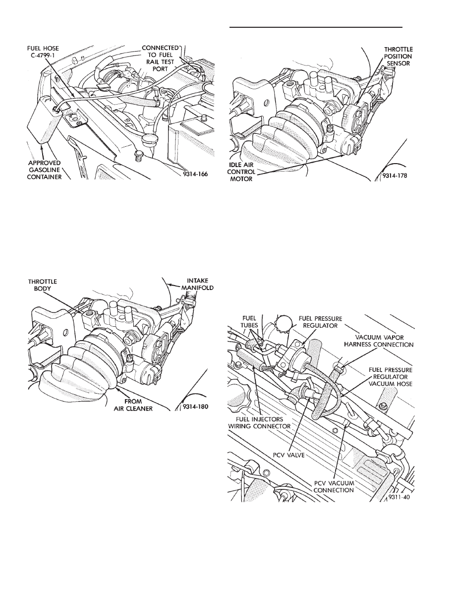
(c) Remove the protective cap from the fuel pres-
sure test port on the fuel rail (Fig. 4).
(d) Place the open end of fuel pressure release
hose, tool number C-4799-1, into an approved gas-
oline container. Connect the other end of hose
C-4799-1 to the fuel pressure test port (Fig. 5).
Fuel pressure will bleed off through the hose into
the gasoline container. Fuel gauge C-4799-A con-
tains hose C-4799-1.
Fig. 4 Fuel Pressure Test Port
Ä
EXHAUST SYSTEM AND INTAKE MANIFOLD
11 - 7
INTAKE MANIFOLD
REMOVAL
(1) Perform fuel system pressure release procedure
before attempting any repairs.
(2) Disconnect negative battery cable.
(3) Remove air cleaner hose to throttle body (Fig.
6).
(4) Remove accelerator and speed control cables.
(5) Disconnect automatic idle speed (AIS) motor
and throttle position sensor (TPS) wiring connectors
(Fig. 7).
(6) Disconnect fuel injectors wiring connector.
(7) Remove supply and return lines from the fuel
tube assembly quick connect at frame rail. Open fuel
tube clip around fuel tubes.
WARNING: WRAP SHOP TOWELS AROUND HOSES
TO CATCH ANY FUEL SPILLAGE.
(8) Disconnect fuel pressure regulator vacuum hose
from regulator (Fig. 8).
(9) Remove PCV vacuum harness, brake booster,
and vacuum vapor harness from intake manifold
(Fig. 8).
(10) Remove 8 intake manifold screws and washer
assemblies and remove intake manifold assembly
(Fig. 9).
Fig. 5 Releasing Fuel Pressure
Fig. 6 Air Cleaner Hose to Throttle Body Assembly
Fig. 7 Throttle Position Sensor and Air Idle Control
Motor Electrical Connections
Fig. 8 Electrical and Vacuum Hose Connection
11 - 8
EXHAUST SYSTEM AND INTAKE MANIFOLD
Ä
Нет комментариевНе стесняйтесь поделиться с нами вашим ценным мнением.
Текст