Chrysler Le Baron, Dodge Dynasty, Plymouth Acclaim. Manual — part 587
(2) Tighten nuts to 52 N
Im (38 ft. lbs.).
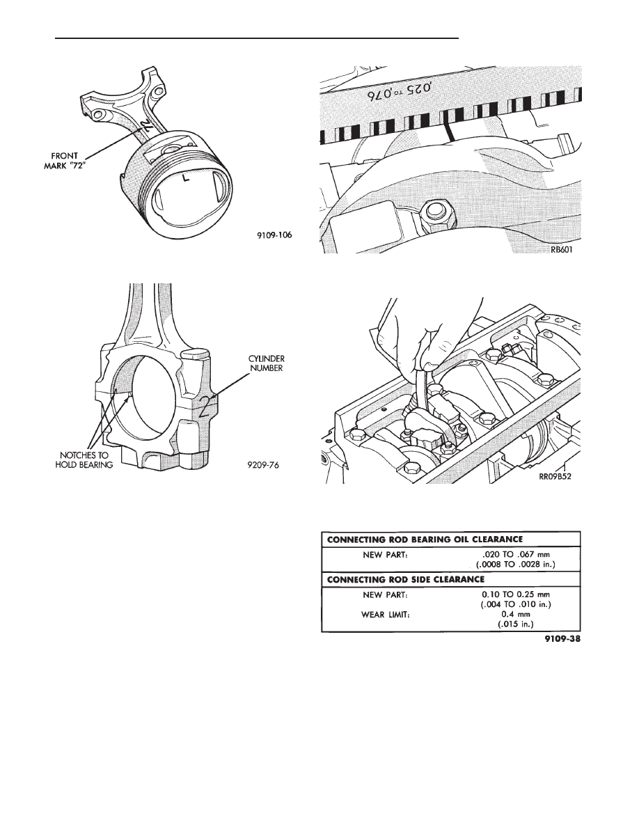
(3) Remove connecting rod cap and measure Plas-
tigage (Fig. 16).
CAUTION: Do not rotate crankshaft or the Plasti-
gage may be smeared.
CONNECTING ROD SIDE CLEARANCE
Using a feeler gauge, check connecting rod side
clearance (Fig. 17). Refer to (Fig. 18) for specifica-
tion.
Fig. 14 Identify Piston/Rod Assembly for Cylinder
Installation
Fig. 15 Connecting Rod and Cap
Fig. 16 Connecting Rod Checking Bearing
Clearance
Fig. 17 Checking Connecting Rod Side Clearance
Fig. 18 Connecting Rod Clearance Specifications
Ä
3.0L ENGINE
9 - 85

CRANKSHAFT AND CYLINDER BLOCK, ASSEMBLY SERVICE
CRANKSHAFT SERVICE
The crankshaft is supported in four main bearings.
All upper bearing shells in the crankcase have oil
grooves. All lower bearing shells in stalled in the
monoblock main bearing cap are plain. Crankshaft
end play is controlled by thrust washers on the num-
ber three main bearing journal.
CRANKSHAFT—REMOVAL
(1) Remove front mounted oil pump assembly and
gasket (Figs. 1 and 2).
(2) Remove rear oil seal retainer and seal as as-
sembly (Fig. 3).
(3) Release monoblock main bearing cap bolts
evenly. Remove lower bearing shells and identify for
reassembly.
(4) Lift out crankshaft and remove upper thrust
washers from each side of number three main bear-
ing in the crankcase (Fig. 1).
INSPECTION
Visually check the main and connecting rod bear-
ing journals for wear, scuffs or scoring and replace if
necessary.
CRANKSHAFT OIL CLEARANCE
MECHANICAL MEASUREMENT
Measure the journal outside diameter and the main
bearing inside diameter (Figs. 4 and 5). If the clear-
ance exceeds the specifications limit (Fig. 6). Replace
the main bearing(s) and if necessary replace the
crankshaft.
Fig. 1 Crankshaft and Cylinder Block
Fig. 2 Oil Pump Assembly
9 - 86
3.0L ENGINE
Ä

PLASTIGAGE MEASUREMENT
(1) Remove oil from journal and bearing shell.
(2) Install crankshaft.
(3) Cut plastigage to same length as width of the
bearing and place it in parallel with the journal axis.
(Fig. 7).
(4) Install the main bearing cap carefully and
tighten the bolts to specified torque.
CAUTION: Do not rotate crankshaft or the plasti-
gage will be smeared.
(5) Carefully remove the bearing cap and measure
the width of the plastigage at the widest part using
the scale on the plastigage package (Fig. 8). Refer to
specification (Fig. 6) for proper clearances. Also see
Measuring Main and Connecting Rod Bearing Clear-
ance in Standard Service Procedures.
CRANKSHAFT BEARINGS
INSTALLATION
(1) Install upper main bearing shells making cer-
tain oil holes are in alignment, and bearing tabs seat
in block tabs. All upper bearings have oil grooves
(Fig. 9).
THRUST BEARINGS. Crankshaft thrust bear-
ings (washers) are installed at journal #3 separately
from the radial bearings. Thrust bearings shown in
Fig. 3 Rear Seal Assembly
Fig. 4 Measure Crankshaft Journal O.D.
Fig. 5 Measure Main Bearing I.D.
Fig. 6 Crankshaft Clearance Specification
Fig. 7 Measure Oil Clearance with Plastigage
Ä
3.0L ENGINE
9 - 87
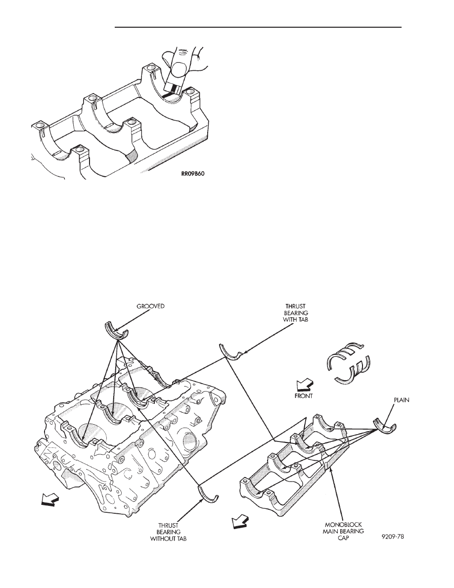
(Fig. 9) are different, one has end positioning tabs,
while the other is plain. One pair of each thrust
washers are installed into the block and one pair
into the main bearing cap (Fig. 9).
(2) Apply a thin film of grease to plain side of
thrust washers and position them on each side of
number three main bearing. Grooved surface towards
crankshaft.
(3) Oil the bearings and journals and install crank-
shaft.
(4) Install lower main bearing shells without oil
grooves in monoblock cap.
(5) Install one pair of thrust washers in cap. Refer
to Thrust Bearings (Fig. 9).
(6) Carefully install bearing cap with arrows (Fig.
10) toward timing belt end.
(7) Oil the bearing cap bolt threads, install and
tighten bolts progressively in sequence shown in
(Fig. 9) to 80 N
Im (60 ft. lbs.) torque.
CHECKING CRANKSHAFT END PLAY
(1) Mount a dial indicator to front of engine, locat-
ing probe on nose of crankshaft (Fig. 11).
(2) Move crankshaft all the way to the rear of its
travel.
(3) Zero the dial indicator.
(4) Move crankshaft all the way to the front and
read the dial indicator. Refer to (Fig. 6) for specifica-
tion.
CRANKSHAFT OIL SEALS SERVICE
REAR CRANKSHAFT SEAL RETAINER
(1) Install rear crankshaft oil seal in housing with
Special Tool MD998718 (Fig. 12).
(2) Apply (Mopar Silicone Rubber Adhesive Seal-
ant or equivalent) to oil seal housing (Fig. 13) per
procedure detailed in form-in-place gasket section in
Standard Service Procedures.
Fig. 9 Install Main Bearings
Fig. 8 Measuring Clearance
9 - 88
3.0L ENGINE
Ä
Нет комментариевНе стесняйтесь поделиться с нами вашим ценным мнением.
Текст