Chrysler Le Baron, Dodge Dynasty, Plymouth Acclaim. Manual — part 323

• If no short to ground at connector, check speaker
resistance at amplifier connector for an reading of
three to five ohms.
• If resistance is OK, refer to Radio Diagnosis. If ra-
dio checks OK, replace amplifier.
• If resistance is less than three ohms check
speaker. Check across the speaker connector if less
than three ohms replace speaker. If resistance is OK
repair wires
CONDITION: MECHANICAL NOISE
DISTORTION
• Check trim for loose parts and speaker attach-
ments for buzzes
• Remove speaker still connected and listen for dis-
tortion. Distortion replace speaker.
CONDITION: ONE SPEAKER NON-OPERATIVE
• Remove output signal connector from amplifier
and check for three to five ohms resistance to the
non-operative speaker. Refer to Fig. 34 for the appro-
priate pin numbers.
• If resistance is less than three ohms, test speaker
for resistance.
• If OK repair wire. If not replace speaker.
CONDITION: ALL SPEAKERS NON-OPERATIVE
• Check radio for being ON, are the display lights
on
• Radio not ON, refer to Radio Diagnosis
• Check Amplifier Connectors and wires for proper
connection
• Check pin 9 and pin 27 for battery voltage
• If voltage OK replace amplifier
• If pin 27 has battery voltage and pin 9 has 0 volt-
age. Refer to Power Antenna Diagnosis and test volt-
age at antenna relay.
• If pin 9 has battery voltage and pin 27 has 0 volt-
age. Check pin 27 for short to ground.
• If shorted to ground repair wire
• If no short to ground check fuse cavity number 16
for blown fuse.
• If fuse blows again replace amplifier
RELAY/CHOKE—INFINITY SPEAKER
If the audio system is lacking bass, check for con-
tinuity across the relay and choke connectors. If no
continuity, replace relay/choke assembly (Fig. 35).
LOCATION
(1) AA and AP Bodies, attached to the reinforce-
ment above glove box.
(2) AG Body, attached to the dimmer module bay-
onet bracket on the bulkhead behind the glove box.
Fig. 35 Relay/Choke Assembly
Ä
AUDIO SYSTEM
8F - 29

COMPACT DISC PLAYER
WARNING: USE OF THE CONTROLS, ADJUST-
MENTS, OR SERVICE PROCEDURES NOT SPECI-
FIED HERE OR IN THE OWNER MANUAL MAY
RESULT IN HAZARDOUS RADIATION EXPOSURE.
REPAIR PROCEDURES SHOULD ONLY BE PER-
FORMED BY A TRAINED TECHNICIAN.
DIAGNOSIS TEST
Power to the compact disc player is supplied by the
radio through the CD interface cable. The compact
disc player will only work with the radio system
turned ON. When a compact disc is inserted with the
label side facing up, the disc is automatically loaded
and will begin to play.
The CD player may eject the disc with a display of
E under the following conditions:
• The surface of the disc is dirty or wet
• The disc was inserted with the label side facing
down
• The disc is defective
• The CD player may skip or mute while playing a
disc under severe vibration conditions example pot
holes, railroad tracks, etc.
• If the CD player becomes too hot at temperatures
above 60°C (140 °F) the CD player will shut down
with a display of HOT until it cools down. Refer to
the Audio Diagnostic Charts.
COMPACT DISC PLAYER REPLACEMENT
With intergral compact disc player refer to Radio
Removal.
AJ BODY
(1) Remove center instrument panel bezel by pull-
ing toward the rear of the car.
(2) Remove two screws attaching disc player to
console (Fig. 36).
(3) Pull disc player out of console and disconnect
interface cable.
(4) To install compact disc player, above the re-
moval procedures.
Fig. 36 Compact Disc Player
8F - 30
AUDIO SYSTEM
Ä
HORNS
CONTENTS
page
page
GENERAL INFORMATION . . . . . . . . . . . . . . . . . . 1
HORN SWITCH REPLACEMENT
. . . . . . . . . . . . 3
TESTING HORN SYSTEM
. . . . . . . . . . . . . . . . . 1
GENERAL INFORMATION
WARNING: ON VEHICLES EQUIPPED WITH AIR
BAG, SEE GROUP 8M, RESTRAINT SYSTEMS FOR
STEERING WHEEL OR COLUMN REMOVAL PROCE-
DURES.
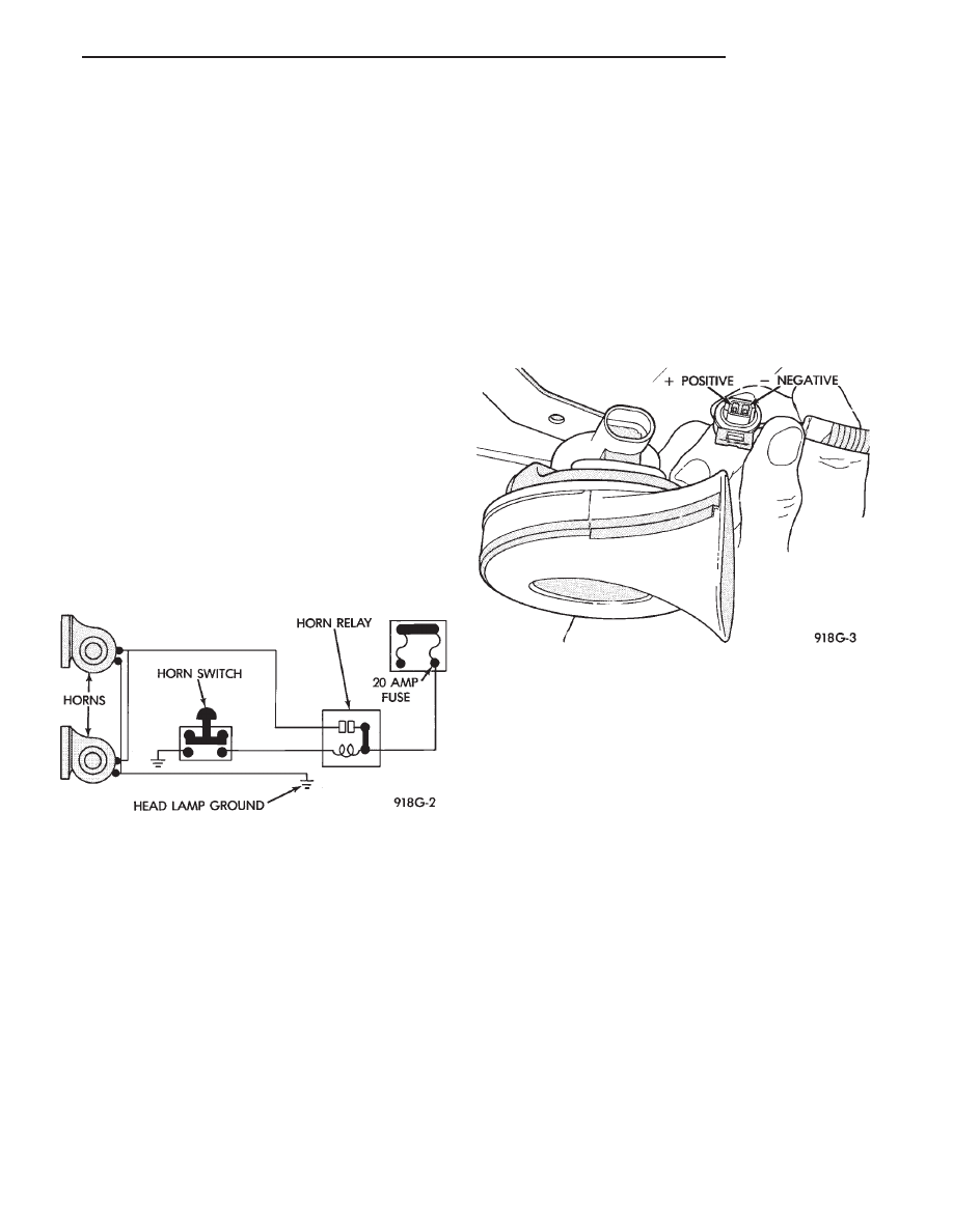
The horn circuit consists of a horn switch, horn re-
lay, and horns. The horn circuit feed is from the fuse
box to the number 1 terminal on the horn relay.
When the horn switch is depressed, this completes
the circuit to ground. This activates the horn relay
and an set of contacts in the relay to close, which al-
lows current to flow to the horn(s). The horn ground
wire is attached to the headlamp ground screw (Fig.
1).
TESTING HORN SYSTEM
HORNS WILL NOT SOUND
If the horns do not sound, check for a blown horn
fuse in the fuse block. If the fuse is blown, replace it
with the same fuse type. If the horns fail to sound
and the new fuse blows when depressing the horn
switch, a short circuit in the horn or the horn wiring
between the fuse terminal and the horn is responsi-
ble.
If the fuse is good, disconnect wire connector at
horn. Using an test lamp, connect one lead to the
negative terminal and the other to the positive ter-
minal (Fig. 2). Depress the horn switch, the test
lamp should illuminate. If not connect the test lamp
wire to a good ground and depress the horn switch. If
test lamp lights inspect ground wire circuit and re-
pair as needed.
If the test lamp fails to illuminate, check for a de-
fective horn relay. Substituting a known good horn
relay in the circuit. If the test lamp illuminates
when depressing the horn switch, the original relay
is defective. If the test lamp fails to illuminate with
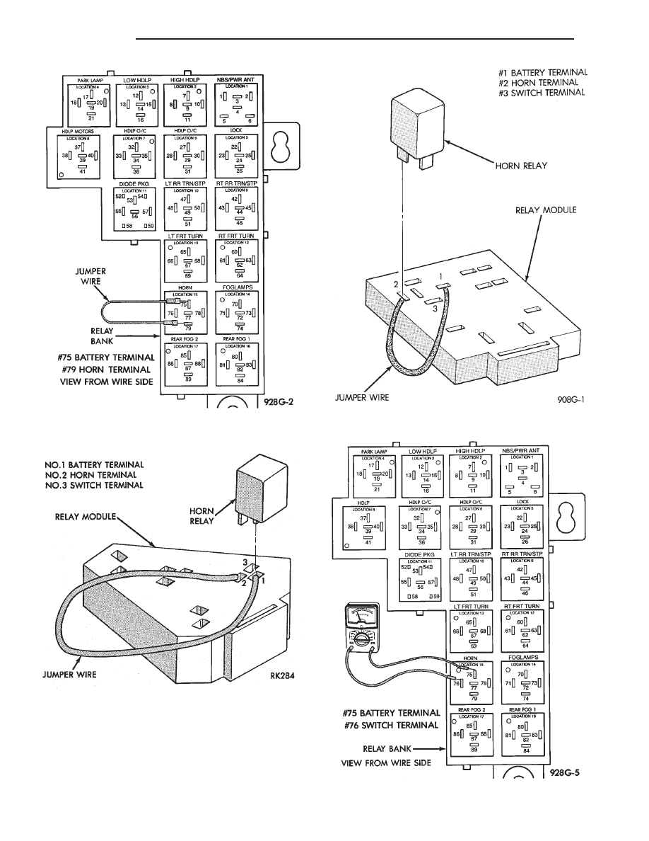
a known good relay, unplug that relay. Connect a
jumper wire from the battery terminal to the horn
terminal on the relay terminal board (Fig. 3, 4, or 5).
If the test lamp connected in place of the horns, fails
to illuminate an open circuit in the wiring between
the relay terminal and the horn switch is at fault re-
pair as necessary.
HORNS SOUND CONTINUOUSLY
CAUTION: Continuous sounding of horns may
cause relay to fail.
Should the horns sound continuously, unplug the
horn relay from the terminal board inside the pas-
senger compartment. Plug in a known good relay. If
the horns stop blowing, relay is defective and must
be replaced. Should the horns still sound, proceed as
follows: Connect one voltmeter lead to battery termi-
nal on relay board and the other lead to switch ter-
minal. Refer to Figs. 6, 7, or 8. Voltmeter will
Fig. 1 Conventional Horn System
Fig. 2 Horn and Connector
Ä
HORNS
8G - 1
register battery voltage when the wire to the horn
switch is shorted to ground or the horn switch is de-
fective.
Fig. 3 Testing for an Open Circuit—AG and AJ Bodies
Fig. 4 Testing for an Open Circuit—AP and AA Bodies
Fig. 5 Testing for an Open Circuit—AC and AY Bodies
Fig. 6 Testing for Short to Ground—AG and AJ Bodies
8G - 2
HORNS
Ä
Нет комментариевНе стесняйтесь поделиться с нами вашим ценным мнением.
Текст