Chrysler Le Baron, Dodge Dynasty, Plymouth Acclaim. Manual — part 333
WIPER SWITCH SERVICE PROCEDURE
WARNING: ON VEHICLES EQUIPPED WITH AIR-
BAG, SEE GROUP 8M, RESTRAINT SYSTEMS FOR
STEERING WHEEL OR COLUMN REMOVAL PROCE-
DURES.
AC AND AY BODIES
The wiper switch is part of the multi-function
switch assembly. If the wiper switch fails, the multi-
function switch must be replaced. Refer to Group 8J,
Turn Signals and Hazard Warning Flasher for multi-
function switch service procedure.
AG AND AJ BODIES
REMOVAL
(1) Remove switch pod assembly from instrument
panel.
(2) Remove five inner switch pod panel.
(3) Unhook switch linkage from buttons.
(4) Remove switch mounting screws.
(5) Remove switch.
INSTALLATION
(1) Latch switch linkage in the up position.
(2) Insert switch into switch pod and install
mounting screws.
(3) Unlatch linkage and install onto push buttons.
(4) Operate all switch modes for correct operation.
(5) Reinstall five inner switch pod panel screws.
(6) Reinstall switch pod assembly.
PULSE INTERMITTENT WINDSHIELD WIPER
CONTROLLER (PIWWC)
The controller is a part of the washing and wiper
system which includes:
• Pulse intermittent windshield wiper controller
• Wiper blades and arms
• Wiper motor
• Windshield washer reservoir
• Wiring harness
• Windshield washer pump
• Windshield washer hoses
Any part not working properly could cause, the
whole system not to work properly or at all. If the
system is not working proper, check all parts before
taking any action of part replacements.
The controller controls the pulse/wipe and the inter-
mittent modes only. The time delay in the intermittent
wipe mode is a minimum of 45 to a maximum of 25 sec-
onds depending on the switch setting.
The wash function can be turn ON with the wiper
control switch in the OFF position. Pressing the
wash button on the end of the level will operate the
washer pump until released. The wipers will operate
while the pump is operating and continue for about
three addition wipes (
61) after before parking.
AA BODY
The PIWWC (Fig. 26) is attached to a bracket lo-
cated to the right of the steering column behind the
steering column cover (Fig. 27).
AP BODY
The PIWWC is attached to a bracket located to the
right of the steering column behind the steering col-
umn cover (Fig. 28).
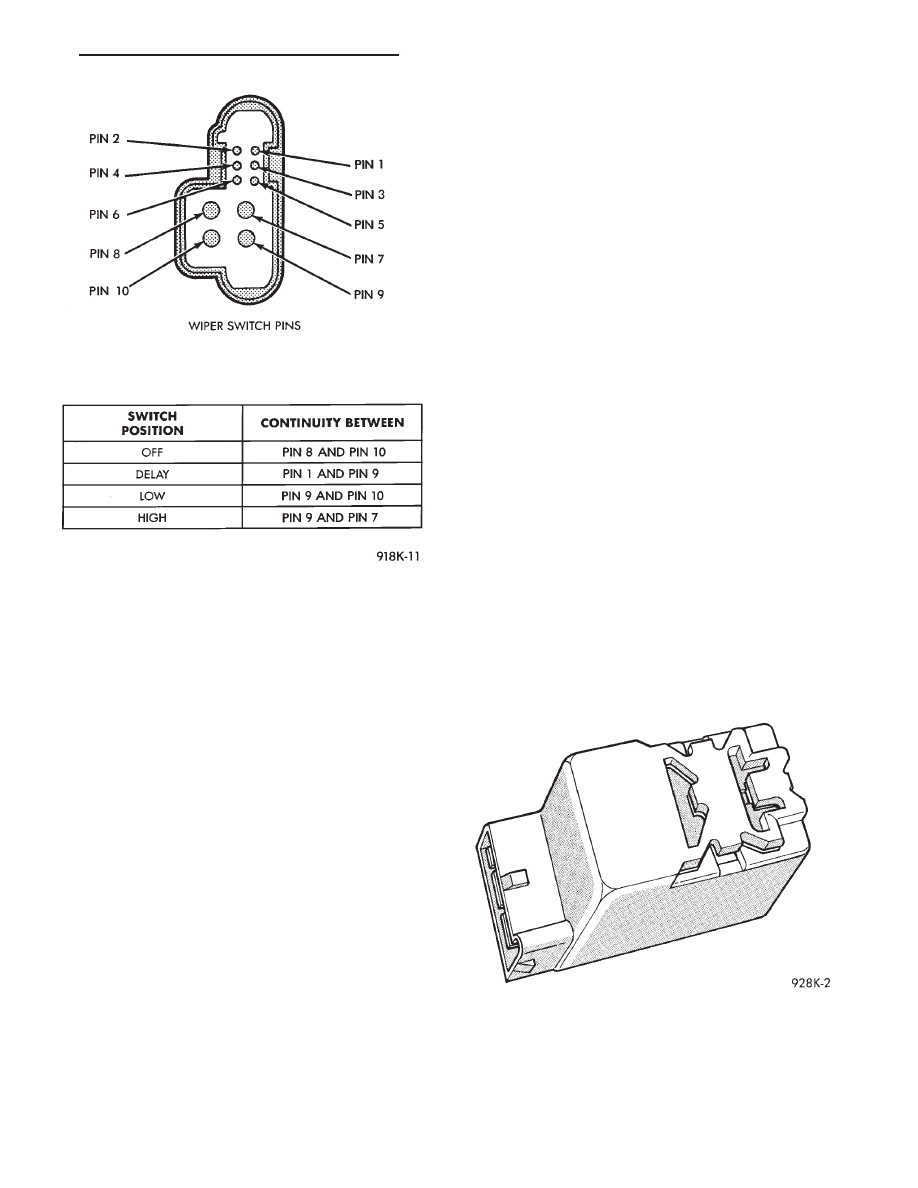
Fig. 25 Front Wiper Continuity—AG and AJ Bodies
Fig. 26 Pulse Intermittent Windshield Wiper
Controller (PIWWC)
Ä
WINDSHIELD WIPER AND WASHER SYSTEMS
8K - 15
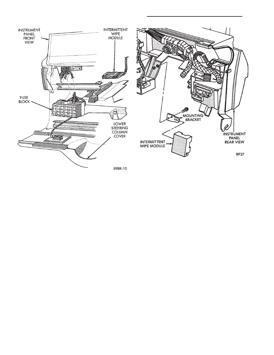
Fig. 27 PIWWC Location AA-Body
Fig. 28 PIWWC Location AP-Body
8K - 16
WINDSHIELD WIPER AND WASHER SYSTEMS
Ä
WINDSHIELD WASHERS
INDEX
page
page
General Information
. . . . . . . . . . . . . . . . . . . . . . . 17
Washer Nozzle
. . . . . . . . . . . . . . . . . . . . . . . . . . 19
Washer Reservoir Pump
. . . . . . . . . . . . . . . . . . . 18
Washer Reservoirs
. . . . . . . . . . . . . . . . . . . . . . . 17
GENERAL INFORMATION
All models are equipped with electric operated
windshield washer pumps.
The wash function can be accessed in the OFF po-
sition of the wiper control switch. Holding the wash
button depressed when the switch is in the OFF po-
sition will operate the wipers and washer motor
pump continuously until the washer button is re-
leased. Releasing the button will stop the washer
pump but the wipers will complete the current wipe
cycle. Then followed by an average of two more wipe
cycles (
61) before the wipers park and the module
turns off.
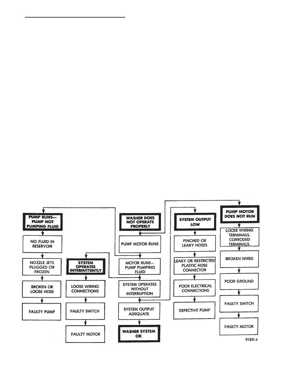
Whenever a windshield washer malfunction occurs,
first verify that the windshield washer wire harness
is properly connected to all connectors before starting
normal diagnosis and repair procedures. Refer to
Windshield Washer Diagnosis Chart (Fig. 29).
The electric pump assembly is mounted directly to
the reservoir. A permanently lubricated sealed motor
is coupled to a rotor type pump. Fluid, gravity fed
from the reservoir, is forced by the pump through
rubber hoses to the nozzles which direct the streams
to the windshield.
The pump and reservoir are serviced as separate
assemblies on all vehicles.
WASHER RESERVOIRS
FRONT WASHER RESERVOIR
REMOVAL
(1) Remove cowl top screen on applicable models
(Fig. 30 through 33)
(2) Remove sheet metal screws attaching the reser-
voir in plenum.
Fig. 29 Windshield Washer Diagnosis
Ä
WINDSHIELD WIPER AND WASHER SYSTEMS
8K - 17
(3) Disconnect the wiring harness from the reser-
voir pump.
(4) Disconnect the washer hose and block the liq-
uid outlet to prevent the liquid from running out
while removing the reservoir from engine compart-
ment.
INSTALLATION
(1) Connect washer hose, wiring harness and in-
stall the reservoir in the plenum chamber.
(2) Install sheet metal attaching screws. Tighten to
3 N
Im (24 in. lbs.) torque.
REAR WASHER RESERVOIR
REMOVAL
(1) Unlock and open liftgate.
(2) Remove right rear quarter panel inside trim as
necessary to gain access to reservoir (Fig. 34).
(3) Remove two reservoir mounting screws.
(4) Disconnect wiring harness and filler tube from
reservoir and pump assembly.
(5) Disconnect the washer hose and block the
pump outlet to prevent liquid from running out.
(6) Remove reservoir and pump assembly from
rear quarter panel.
INSTALLATION
(1) Position reservoir and pump assembly into the
right rear quarter panel.
(2) Connect washer hose, wire harness and filler
tube to the reservoir and pump assembly.
(3) Install two reservoir mounting screws.
(4) Install right rear quarter panel inside trim.
WASHER RESERVOIR PUMP
FRONT WASHER RESERVOIR PUMP
REMOVAL
(1) Remove liquid from reservoir.
(2) Remove reservoir mounting screws and remove
reservoir and pump assembly (Fig. 30 through 33).
(3) Disconnect electrical lead and rubber hose from
bottom of pump.
(4) Gently pry pump away from reservoir and out
of grommet. Care must be taken not to puncture res-
ervoir.
(5) Remover rubber grommet from reservoir and
throw away.
INSTALLATION
(1) Install new rubber grommet on reservoir.
(2) Position pump into place, and push in firmly
until it locks into grommet.
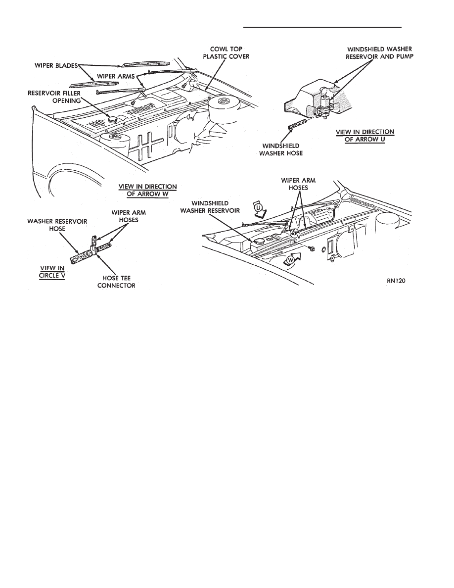
Fig. 30 Windshield Washer System—AG and AJ Bodies
8K - 18
WINDSHIELD WIPER AND WASHER SYSTEMS
Ä
Нет комментариевНе стесняйтесь поделиться с нами вашим ценным мнением.
Текст