Chrysler Le Baron, Dodge Dynasty, Plymouth Acclaim. Manual — part 279
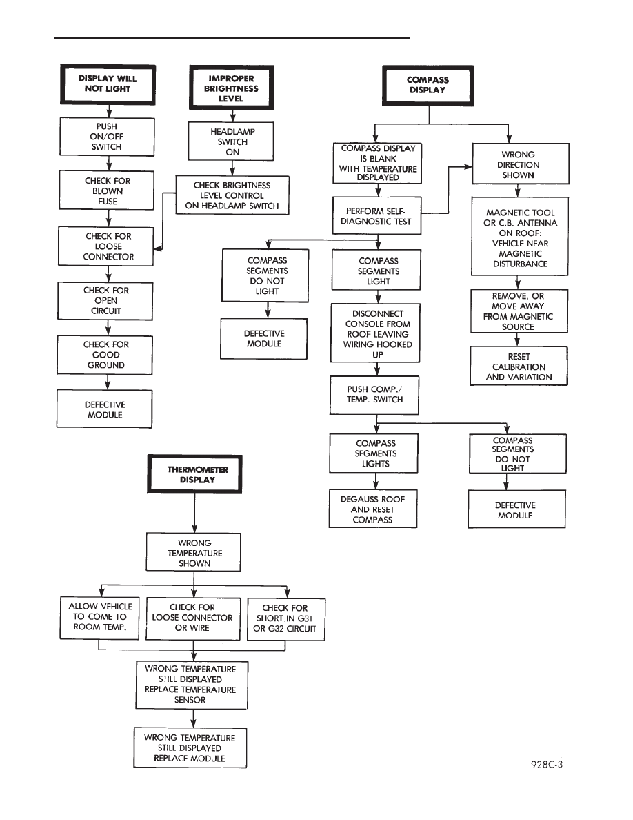
Fig. 3 Compass and Thermometer Diagnosis
Ä
OVERHEAD CONSOLE
8C - 3
VARIANCE SETTING PROCEDURE
There are two methods for setting variance while
in variance set mode. If the CAL symbol is on proce-
dure 2 must be used.
PROCEDURE 1
(1) Turn ignition switch to the on position.
(2) Press and hold the Comp/Temp button till the
display is turned OFF.
(3) While continuing to hold Comp/Temp button
depress and hold US/Metric button until the VAR
symbol lights in approximately 5 seconds.
(4) Release buttons.
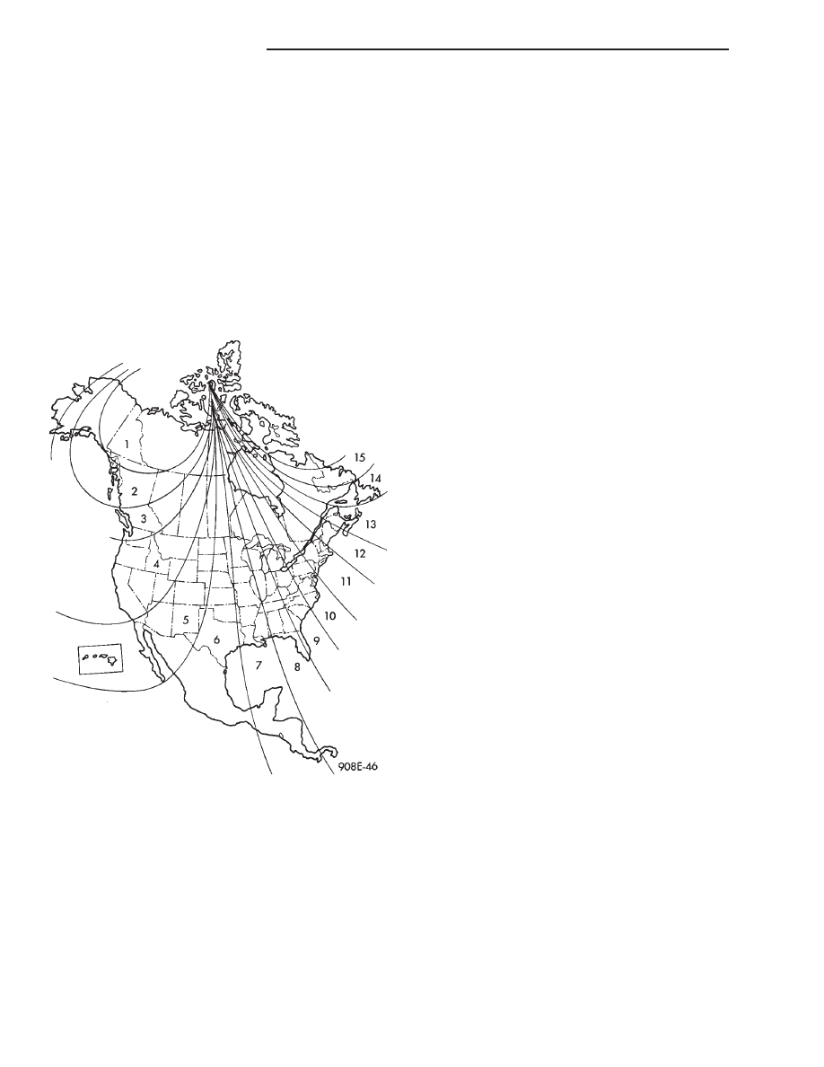
(5) To determine the zone number which, corre-
sponds with your geographic area refer to Fig. 4.
(6) Press the US/Metric button until the zone num-
ber matches the display.
(7) Press the Comp/Temp button to finish setting
of variation.
(8) Variation is complete.
PROCEDURE 2
(1) Move away from any large metal objects like
buildings, or bridges. With the engine running and
the doors closed point vehicle true north.
(2) Press and hold Comp/Temp button. The display
will go blank.
(3) While continuing to hold Comp/Temp button
depress and hold the US/Metric button until the
VAR symbol lights in approximately 5 seconds.
(4) Release buttons.
(5) Press the Comp/Temp button to finish setting
of variation.
(6) Variation is complete.
DEMAGNETIZING PROCEDURE
Do not attach magnetic devices, such as magnetic
CB antennas to the vehicle roof, as they can cause
the compass to give false readings.
Every vehicle has its own magnetic field. This
magnetic field is created by the various processes a
steel roof goes through when the vehicle is built. A
magnetic field also can be created if the roof is sub-
jected to A magnet, example:
• Magnetic c.b. antenna
• Magnetic tipped screwdriver and etc.
If the roof becomes magnetized use a demagnetiz-
ing Tool 6029 to demagnetize the roof.
In this demagnetizing procedure you will use the
demagnetizing tool to demagnetize the roof and
mounting screws in the overhead console. It is impor-
tant that you follow the instructions below exactly.
The mounting screws and the mounting brackets
around the compass area are steel, and therefore aid
in the degaussing of the roof panel.
(1) Be sure the ignition switch is in the OFF posi-
tion before you begin the demagnetizing procedure.
(2) Open the sun glass compartment to gain access
to the overhead console mounting screws.
(3) Plug the demagnetizing tool into a standard
110/115 volt AC outlet, keeping the demagnetizing
tool at least 12 inches away from the compass area
when plugging it in.
(4) Slowly approach the console mounting screw
with the plastic coated tip of the tool for at least 2
seconds.
(5) With the demagnetizing tool still energized,
slowly back it away from the screw until the tip is at
least 12 inches from the screw head.
(6) After you have pulled at least 12 inches from
the last screw, remove the demagnetizing tool from
inside of the vehicle and disconnect it from the elec-
trical outlet.
(7) Place an 8 1/2 in. X 11 in. piece of paper
lengthwise on the roof of vehicle directly above com-
pass. The purpose of the paper is to protect the roof
panel from scratches and define the area to be de-
magnetized.
Fig. 4 Variance Settings
8C - 4
OVERHEAD CONSOLE
Ä
(8) Plug in the demagnetizing tool, keeping it at
least 2 feet away from the compass unit.
(9) Slowly approach the center of the roof panel at
the windshield with the demagnetizing tool plugged
in.
• Contact the roof panel with the tip of the tool.
• Using slow sweeping motions of 1/2 inch between
sweeps
• Move the tool approximately 4 inches either side of
the centerline, and at least 11 inches back from the
windshield.
(10) With the demagnetizing tool still energized,
slowly back away from the roof panel until the tip is
at least two feet from the roof before unplugging the
tool.
(11) Recalibrate compass.
COMPASS DIAGNOSTICS
To place the unit into the diagnostics mode, turn
the vehicle ignition off. Depress the Comp/Temp but-
ton while turning on the ignition/run switch. The
display will then show DO. There are three tests that
can be performed when in the diagnostics mode.
Press the U.S./Metric button to choose test desired
(Fig. 5).
Test 1 (d1) determines the magnetic field strength
at the compass. The compass displays compensation
numbers which, correspond to the current magnetic
field strength at the compass. The letter N is dis-
played in the compass portion of the display. While a
number which, corresponds to the magnetic field
strength in the North/South direction is displayed.
The temperature portion of the display or the letter
W is displayed in the compass portion of the display.
A number which, corresponds to the magnetic field
strength in the East/West direction is displayed in
the temperature portion of the display. For proper
compass operation the numbers should be between 1
and 14. A number of 7 or 8 is ideal (no vehicle mag-
netism) while numbers approaching 1 or 14 show
that the vehicle is highly magnetic. If the numbers
show that the vehicle is highly magnetic, perform
the demagnetized procedure in this Group and retest
for magnetism at compass.
Test 2 (d2) checks the electronic circuits of the
compass, temperature. If the test passes d2 will be
displayed, and if the test fails F2 will be displayed.
Refer to Body Diagnostic Procedure Manual for fur-
ther testing procedures.
Test 3 (d3) performs a walking segment test which,
sequentially puts different directions and numbers on
the display. If any segment fails, replace the compass
module.
SELF-DIAGNOSTIC TEST
(1) With the ignition switch in the OFF position si-
multaneously press the Comp/Temp button and the
US/Metric button.
(2) Turn ignition switch ON.
(3) Continue to hold both buttons until the display
performs a walking segment test. This checks for
open or shorted segments. To repeat the test press
the Comp/Temp button.
(4) Press the US/Metric button, all segments will
light for about 2 seconds. To repeat the test press the
Comp/Temp button.
(5) Press the US/Metric button to return to normal
operation.
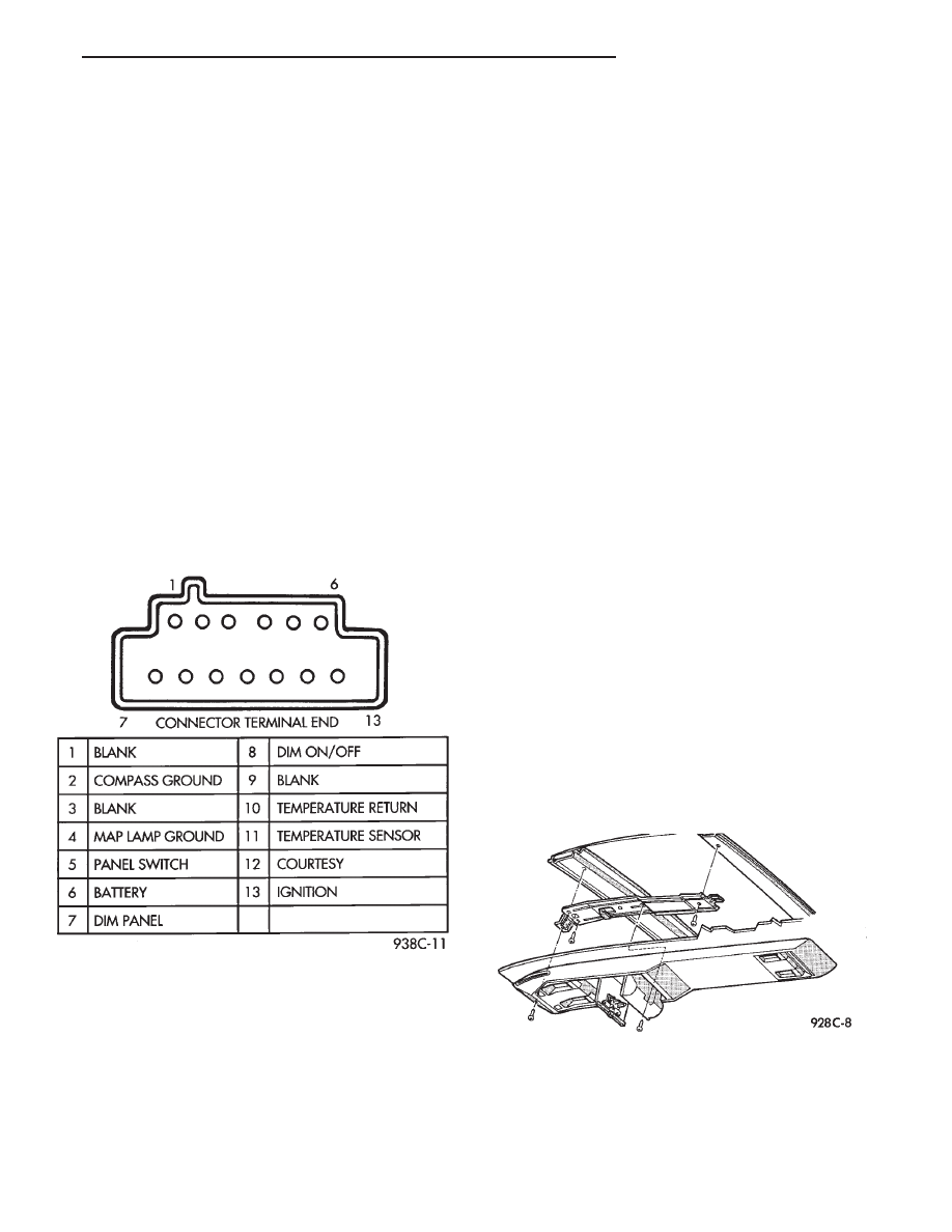
OVERHEAD CONSOLE REPLACEMENT
(1) Unscrew the mounting screw in sun glass bin
compartment (Fig. 6).
(2) Slide console forward toward windshield until
the console unhooks from roof bracket.
(3) Disconnect wire harness from console.
(4) For installation reverse above procedures.
Fig. 5 Terminal Identification
Fig. 6 Overhead Console Mounting
Ä
OVERHEAD CONSOLE
8C - 5
COMPASS MODULE REPLACEMENT
(1) Remove overhead console.
(2) Using a small screwdriver, release the 2 snaps
at rear of compass module.
(3) After releasing the 2 snaps, slide compass mod-
ule rearward until free of mounting bar.
(4) For installation reverse above procedures.
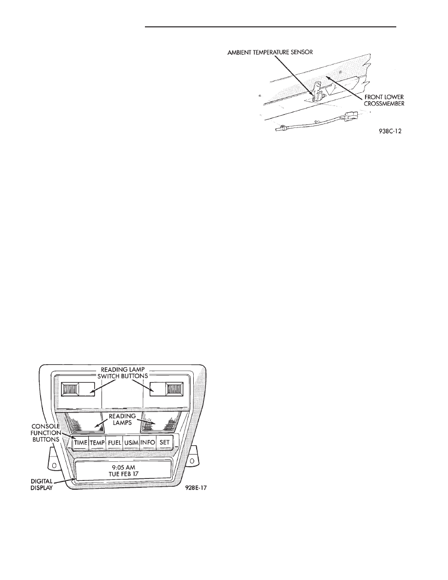
AMBIENT TEMPERATURE SENSOR
(1) Raise and support vehicle on safety stands.
(2) From behind front bumper fascia, remove screw
attaching sensor to front lower crossmember (Fig. 7).
(3) For installation, reverse above procedures.
AC AND AY BODY
INDEX
page
page
Ambient Temperature Sensor
. . . . . . . . . . . . . . . 12
Automatic Calibration Set Procedure
. . . . . . . . . . . 8
Bezel/Button Switch Removal
. . . . . . . . . . . . . . . 10
Bus Accessed Diagnostics
. . . . . . . . . . . . . . . . . . 10
Console Removal
. . . . . . . . . . . . . . . . . . . . . . . . 10
Electronic Board Assembly Replacement
. . . . . . . 10
Electronic Vehicle Information Center (EVIC)
Overhead Console
. . . . . . . . . . . . . . . . . . . . . . . 6
Engine Compartment Node Removal
. . . . . . . . . . 12
EVIC Self Check Diagnostics
. . . . . . . . . . . . . . . . 8
Manual Calibration Set Procedure
. . . . . . . . . . . . . 8
Map Reading Lamps/Power Sunroof Switch
Removal
. . . . . . . . . . . . . . . . . . . . . . . . . . . . . . 11
Overhead Reading/Courtesy Lamp Console
. . . . . 11
Wiring Harness Removal
. . . . . . . . . . . . . . . . . . . 10
ELECTRONIC VEHICLE INFORMATION CENTER
(EVIC) OVERHEAD CONSOLE
The Electronic Vehicle Information Center is a
computer controlled warning system which, monitors
various sensors used on the vehicle. The system sup-
plements the warning indicators in
8the instrument
cluster. Visual warning messages are displayed by a
digital display in the overhead console (Fig. 1).
When a warning message has been activated, a
tone will sound to attract the driver’s attention. The
warning message will then be displayed on the over-
head console until the condition is corrected or a new
display function is called up. A tone will announce
each new warning condition.
For complete diagnostic procedures for the EVIC
systems, refer to the Body-Chassis Diagnostic Test
Procedures Manual.
The EVIC has a 24 function system that provides
the driver with visual messages when a warning con-
dition exists. These messages are displayed on the
overhead console.
For complete EVIC overhead console operating in-
structions, refer to the Owners Manual provided with
the vehicle.
EVIC BUTTON FUNCTIONS
TIME button will display:
• Time of day
• Day of week
• Day of month
• Month of year
The body controller is the source of this informa-
tion. The EVIC function buttons are used to reset
and display this data.
• To set HOURS, press TIME button and within four
seconds press the SET button. An arrow will appear
on the display and point to the hours. Press and hold
the SET button to advance the hours or INFO button
to set back the hours.
• To set MINUTES, press TIME button. The arrow
will point to the minutes. Press and hold the SET
button to advance the minutes or INFO button to set
back the minutes.
Fig. 7 Ambient Temperature Sensor
Fig. 1 EVIC Overhead Console
8C - 6
OVERHEAD CONSOLE
Ä
Нет комментариевНе стесняйтесь поделиться с нами вашим ценным мнением.
Текст