Chrysler Le Baron, Dodge Dynasty, Plymouth Acclaim. Manual — part 298
SENDING UNIT TEST
When a problem occurs with a cluster gauge, be-
fore disassembling the cluster to check the gauge,
check for a defective sending unit or wiring.
(1) Sending units and wiring can be checked by
grounding the connector leads, at the sending unit,
in the vehicle.
(2) With the ignition in the ON position; a
grounded input will cause the oil, fuel or tempera-
ture gauge to read at or above maximum.
LOW OIL PRESSURE/CHECK GAUGES
WARNING LAMP TEST
The low oil pressure/check gauges warning lamp
will illuminate when the ignition key is turned to
the ON position without starting the vehicle.
In the cluster assembly without tachometer, the
low oil pressure lamp will illuminate if the engine oil
pressure drops below a safe oil pressure level.
In the cluster assembly with tachometer, the Check
Gauges warning lamp illuminates when there is a
problem in oil pressure level, high engine tempera-
ture or low voltage.
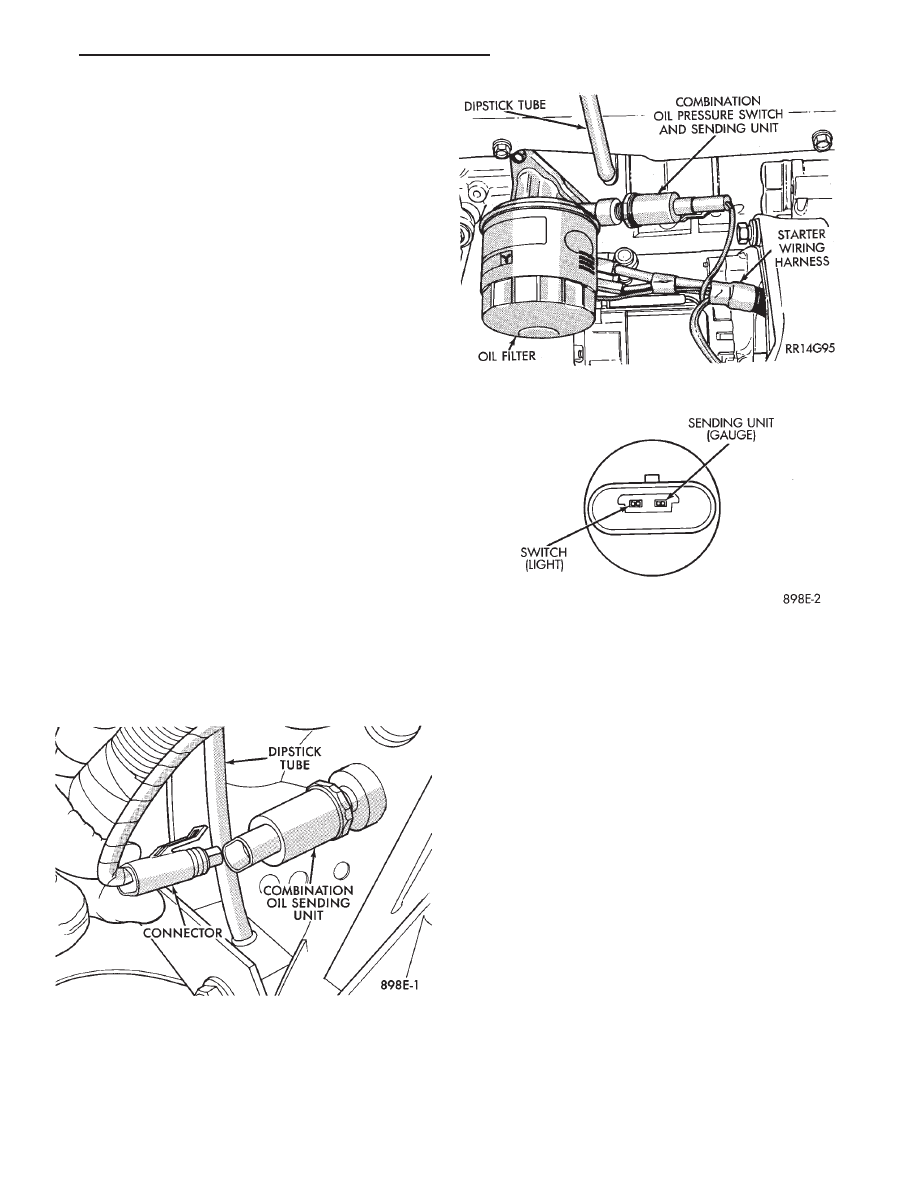
To test the system turn ignition key to the ON po-
sition. If the lamp fails to light, inspect for a broken
or disconnected wire at the oil pressure combination
unit, which is located at the front of the engine (Figs.
5 and 6). If the wire at the connector checks good,
pull connector loose from the switch terminal and
with a jumper wire ground connector to the engine
(Fig. 7). With the ignition key turned to the ON po-
sition check the warning lamp. If lamp still fails to
light, inspect for a burned out lamp or disconnected
socket in the cluster.
COMBINATION OIL UNIT TEST
The combination oil unit has two functions:
(1) The normal closed circuit keeps the oil pressure
warning/check gauges lamp on until there is oil pres-
sure (Fig. 7).
(2) The sending unit provides a resistance that
varies with oil pressure.
(3) To test the normally closed oil lamp circuit, dis-
connect the locking connector and measure the resis-
tance between the switch terminal and the metal
housing. The ohmmeter should read 0 ohms. Start
the engine.
(4) If there is oil pressure, the ohmmeter should
read an open circuit.
(5) To test the sending unit, measure the resis-
tance between the sending unit terminal and the
metal housing. The ohmmeter should read open.
Start the engine.
(6) The ohmmeter should read between 30 to 55
ohms, depending on engine speed, oil temperature,
and oil viscosity.
(7) If the above results are not obtained, replace
the switch.
BRAKE SYSTEM WARNING LAMP TEST
The brake warning lamp illuminates when parking
brake is applied with ignition key turned ON. The
same lamp will also illuminate should one of the two
service brake systems fail when brake pedal is ap-
plied. To test system turn ignition key ON, and ap-
ply parking brake. If lamp fails to light, inspect for a
burned out lamp, disconnected socket, a broken or
Fig. 5 Combination Oil Unit (2.5L)
Fig. 6 Combination Oil Unit (3.0L)
Fig. 7 Combination Oil Unit Test
Ä
INSTRUMENT PANEL AND GAUGES
8E - 3
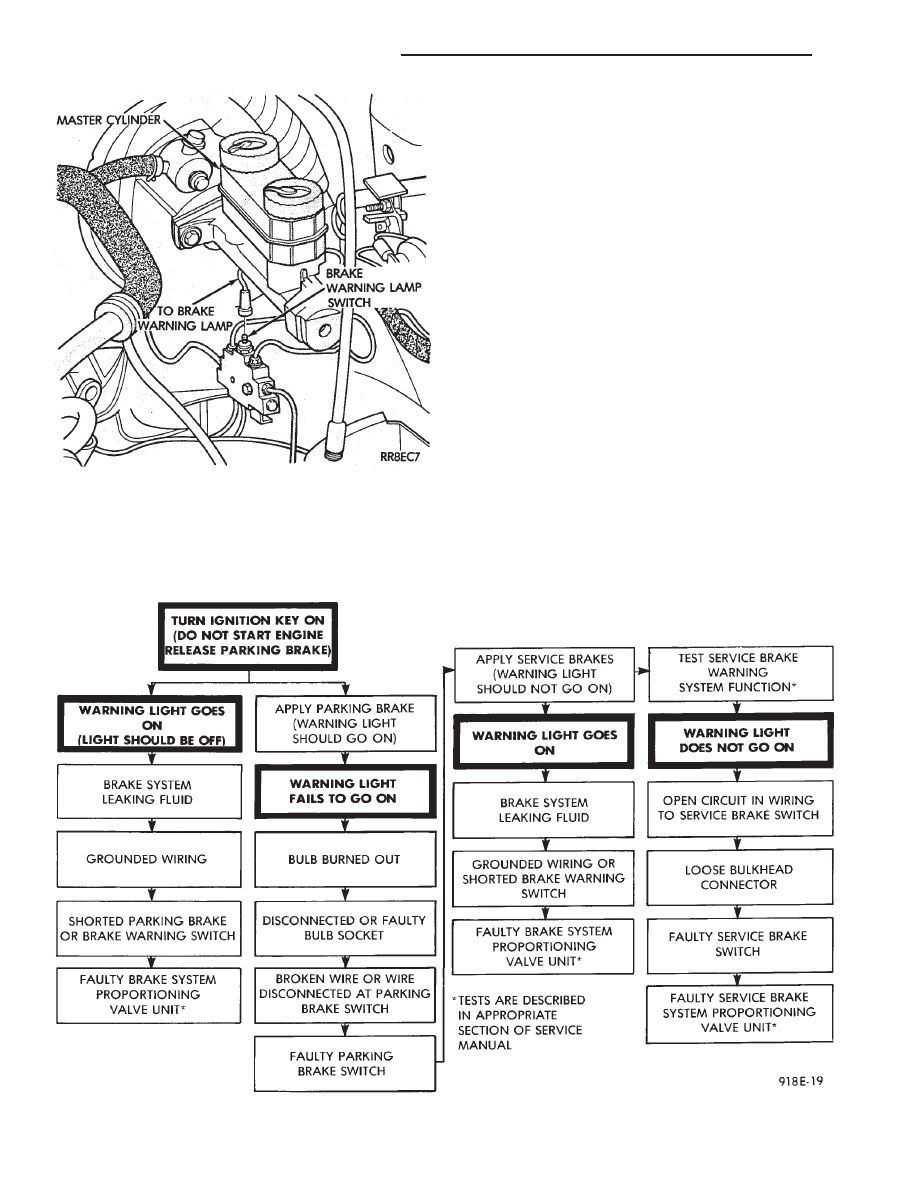
disconnected wire at switch. The lamp also lights
when the ignition switch is turned to START.
To test service brake warning system, raise vehicle
on a hoist and open a wheel cylinder bleeder while a
helper depresses brake pedal and observes warning
lamp. If lamp fails to light, inspect for a burned out
lamp, disconnected socket, a broken or disconnected
wire at switch.
If lamp is not burned out and wire continuity is
proven, replace brake warning switch in brake line
Tee fitting mounted on frame rail in engine compart-
ment below master cylinder (Fig. 8 and 9).
CAUTION: If wheel cylinder bleeder was opened
check master cylinder fluid level.
SEAT BELT WARNING SYSTEM
For testing of this system refer to Group 8M, Re-
straint Systems.
MALFUNCTION INDICATOR (CHECK ENGINE)
SYSTEM
For testing this system refer to the Powertrain Di-
agnostic Test Procedures booklet.
AIR BAG WARNING SYSTEM
For testing this system refer to Group 8M, Re-
straint Systems.
Fig. 8 Brake Warning Lamp Switch
Fig. 9 Brake System Warning Lamp Diagnosis
8E - 4
INSTRUMENT PANEL AND GAUGES
Ä

MECHANICAL/ELECTRONIC CLUSTER REMOVAL
CLUSTER BEZEL REMOVAL
(1) On column shift vehicles, place column shifter
to neutral position.
(2) On tilt steering column vehicles, adjust tilt
range to lowest position.
(3) Pull cluster bezel rearward to disengage 11
clips (Fig. 10).
(4) Remove cluster bezel.
(5) For installation reverse above procedures.
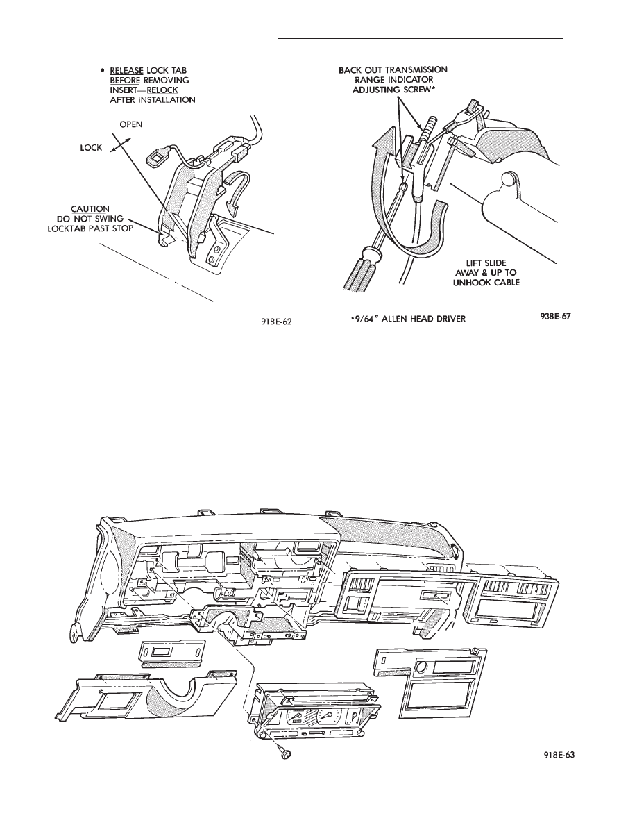
CLUSTER MASK AND LENS REMOVAL
(1) Remove cluster, radio and rear window defog-
ger bezels (Fig. 10).
(2) Remove four cluster to panel screws.
(3) Pull cluster assembly rearward. Vehicles with
column shift use care to not damage transmission
range indicator guide tube.
(4) Remove four screws holding the cluster mask to
cluster housing (Fig. 11).
(5) Pull cluster mask and lens rearward to remove.
(6) For installation reverse above procedures.
CLUSTER ASSEMBLY
REMOVAL—CLUSTER WITH TRANSMISSION RANGE
INDICATOR FROM STEERING COLUMN
(1) Disconnect battery to assure no air bag system
fault codes are stored.
(2) Remove cluster bezel (Fig. 10).
(3) On column shift vehicle: (Fig. 12 through 15).
(a) Remove lower steering column cover (Fig.
16). Release guide tube from behind fuse block.
Fig. 10 Cluster Bezel
Fig. 11 Cluster Mask and Lens
Fig. 12 Transmission Range Indicator Step 1
Fig. 13 Transmission Range Indicator Step 2
Ä
INSTRUMENT PANEL AND GAUGES
8E - 5
(b) Place gear shift lever in neutral or park.
(c) Remove guide tube from behind fuse block
and disconnect cable eyelet from column actuating
arm.
(d) Release lock bar on column insert, squeeze
legs together and remove from column (Fig. 14).
(e) Secure insert and cable guide out of the way.
(4) Remove the rear window defogger bezel and ra-
dio bezel.
(5) Remove the upper steering column cover.
(6) Remove the four screws attaching cluster hous-
ing to the base panel.
(7) Pull cluster rearward, reach behind cluster and
disconnect the two wiring harnesses.
(8) Remove cluster assembly.
INSTALLATION
(1) Connect wiring harnesses.
(2) Position cluster and secure to base panel with
four screws.
(3) On column shift vehicles (Fig. 12 through 15):
Fig. 15 Transmission Range Indicator Step 4
Fig. 16 Instrument Panel Bezels
Fig. 14 Transmission Range Indicator Step 3
8E - 6
INSTRUMENT PANEL AND GAUGES
Ä
Нет комментариевНе стесняйтесь поделиться с нами вашим ценным мнением.
Текст