Chrysler Le Baron, Dodge Dynasty, Plymouth Acclaim. Manual — part 84
(2) Slide the tripod back along the shaft, either by
hand or by tapping the body with a brass drift. This
will expose the circlip on the end of the interconnect-
ing bar.
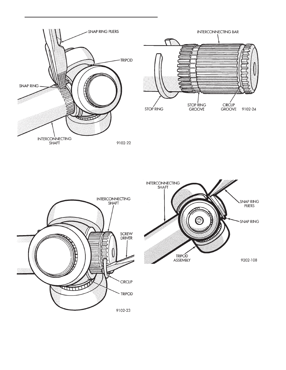
(3) Remove the circlip from the end of intercon-
necting bar (Fig. 6).
(4) Remove the tripod from the interconnecting
bar. It is not necessary to remove the stop ring from
the interconnecting bar unless the bar is being re-
placed (Fig. 7).
S.S.G. AND G.K.N. WITH SINGLE RING TRIPOD
RETENTION.
Remove the tripod assembly to interconnecting
shaft retaining snap ring from the interconnecting
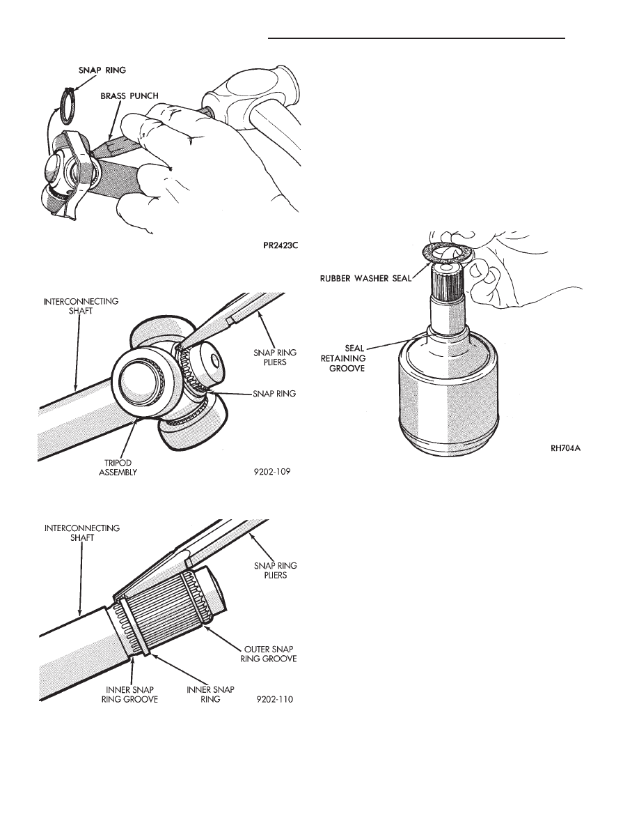
shaft end groove (Fig. 8). Remove the tripod assem-
bly from the interconnecting shaft by hand or by tap-
ping the body of the tripod assembly with a brass
punch (Fig. 9).
G.K.N. WITH DOUBLE RING TRIPOD RETENTION.
(1) Expand and remove the outer tripod assembly
to interconnecting shaft, retaining snap ring (Fig.
10).
(2) Remove the tripod assembly from the intercon-
necting shaft. Tripod can be removed either by hand
or by tapping the tripod body with a brass drift (Fig.
4). Do not hit the outer tripod bearings in an attempt
to remove tripod assembly from interconnecting
shaft.
(3) Remove inner tripod assembly to interconnect-
ing shaft, retaining snap ring from interconnecting
shaft (Fig. 11).
Fig. 5 Removing Stop Ring (G.K.N.)
Fig. 6 Removing Circlip
Fig. 7 Tripod Removed From The Interconnecting
Bar
Fig. 8 Outer Tripod Retaining Snap Ring Removal
Ä
SUSPENSION AND DRIVESHAFTS
2 - 33
INSPECT TRIPOD AND HOUSING
Remove as much grease as possible from assembly
and inspect joint housing ball raceway and tripod
components for EXCESSIVE wear and replace if nec-
essary.
Inspect the spring, spring cup, and the spherical end
of the connecting shaft for EXCESSIVE wear or dam-
age and replace, if necessary.
ASSEMBLE C/V JOINT
TRIPOD ASSEMBLY INSTALLATION G.K.N.
(1) Slide rubber washer seal over stub shaft and
down into the groove provided (Fig. 12). The rubber
washer seal is used only on the right inner C/V
joint on the Equal Length Drive Shaft Systems.
(2) Fasten the (new) boot to the interconnecting
shaft. See Boots Install.
(3) Slide the stop ring back into the stop ring groove
on the interconnecting bar (Fig. 5).
(4) Install a new circlip in the circlip groove on the
interconnecting bar (Fig. 6).
(5) With the chamfered end (Fig. 13 & 14 ) of the
tripod facing the stop ring. Align the tripod splines and
push or tap on the body of the tripod assembly with a
SOFT drift, until tripod is seated on the shaft.Check
to make sure that the Tripod is Engaged by
attempting to pull the tripod off of the shaft by
hand.
TRIPOD ASSEMBLY INSTALLATION S.S.G.
(1) Slide rubber washer seal over stub shaft and
down into the groove provided (Fig. 12). The rubber
washer seal is used only on the right inner C/V
joint on the Equal Length Drive Shaft Systems.
(2) Fasten the (new) boot to the interconnecting
shaft. See Boots Install.
(3) Install first wire ring tripod retainer over inter-
connecting shaft, slide tripod on the shaft, both ends
are the same (Fig. 15).
Fig. 9 Tripod Assembly Removal From
Interconnecting Shaft
Fig. 10 Removing Outer Tripod Retaining Snap Ring
(G.K.N.)
Fig. 11 Removing Inner Tripod Retaining Snap Ring
(G.K.N.)
Fig. 12 Rubber Washer Seal Installation
2 - 34
SUSPENSION AND DRIVESHAFTS
Ä
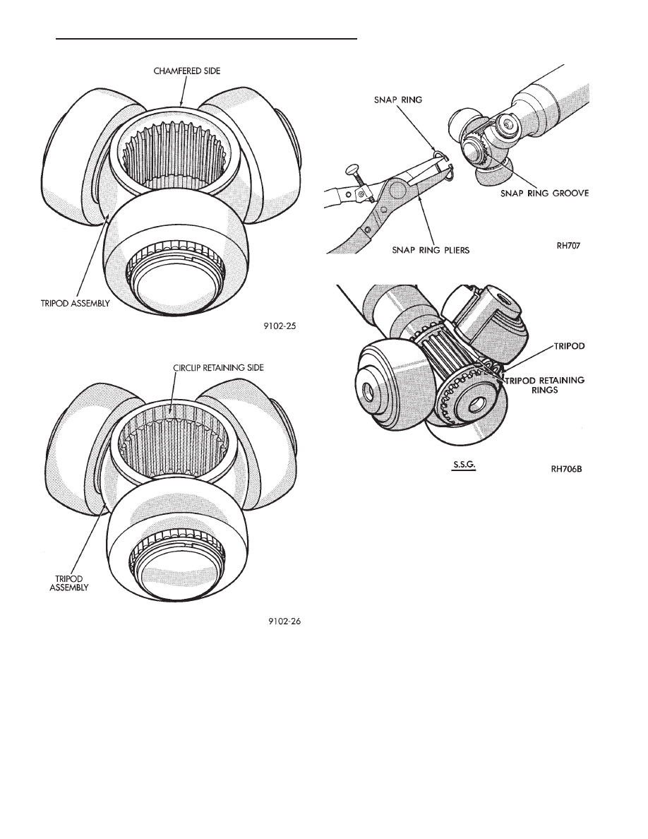
(4) Install the snap ring into the groove on the in-
terconnecting shaft to lock the tripod in position (Fig.
16)
Should the wire ring tripod retainer not be suitable
for reuse or a new one is not available,the following
procedure should be used:
(1) Install tripod on the shaft.
(2) Install spring and cup assembly into inner joint
housing.
(3) Position small end of boot in locating grooves
on the interconnecting shaft.
(4) Clamp the small end boot clamp onto boot, re-
taining boot to the interconnecting shaft.
(5) Distribute 1/2 packet of grease into boot and
1/2 into housing.
(6) Install tripod into housing.
(7) Place large clamp over shaft.
(8) Install driveshaft into vehicle, see Driveshaft
Install.
(9) Position large end of boot into locating groove.
(10) Slide large clamp into position.
(11) See Boot Install for clamping instructions.
TRIPOD ASSEMBLY INSTALLATION S.S.G. & G.K.N. WITH
SINGLE RING RETENTION
(1) Fasten the (new) boot to the interconnecting
shaft. See Boots Install.
(2) Install the tripod assembly onto the intercon-
necting shaft until it is past the snap ring groove on
the shaft (Fig. 17). If required the tripod assembly
can be tapped onto the interconnecting shaft using a
brass drift, on the body of the tripod assembly (Fig.
4). Do not hit the outer tripod assembly bearings in
an attempt to install tripod on interconnecting shaft.
Fig. 13 G.K.N. Tripod Thick Ring Side
Fig. 14 G.K.N. Tripod Circlip Side
Fig. 15 Tripod Snap Ring Installation
Fig. 16 Tripod Installation
Ä
SUSPENSION AND DRIVESHAFTS
2 - 35
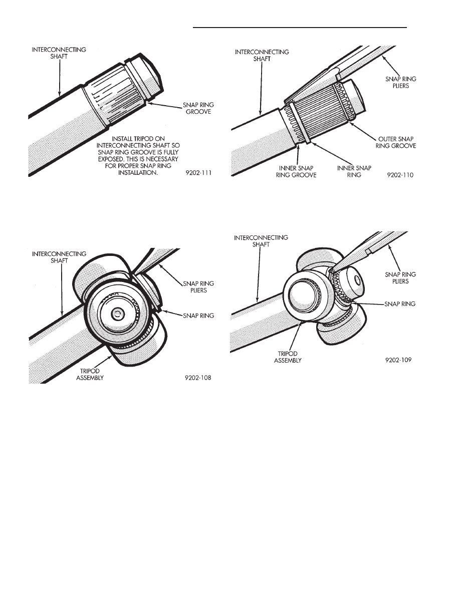
(3) Install a NEW outer tripod assembly to inter-
connecting shaft retaining snap ring, into intercon-
necting shaft snap ring groove (Fig. 18). Be sure that
the snap ring is fully seated into the snap ring
groove around the entire interconnecting shaft.
TRIPOD ASSEMBLY INSTALLATION G.K.N. WITH DOUBLE
RING RETENTION
(1) Fasten the (new) boot to the interconnecting
shaft. See Boots Install.
(2) Install the inner tripod assembly retaining
snap ring into the retaining groove on the intercon-
necting shaft (Fig. 19).
(3) Install the tripod assembly onto the intercon-
necting shaft until it is past the outer snap ring
groove on the shaft (Fig. 17). If required the tripod
assembly can be tapped onto the interconnecting
shaft using a brass drift, on the body of the tripod as-
sembly (Fig. 4). Do not hit the outer tripod assembly
bearings in an attempt to install tripod on intercon-
necting shaft.
(4) Install outer tripod assembly to intermediate
shaft retaining snap ring into snap ring groove on
intermediate shaft (Fig. 20).
INNER C/V JOINT HOUSING INSTALLATION
G.K.N.
(1) Distribute 1/2 the amount of the grease provided
into the housing and the remaining amount into the
boot.
(2) Position the spring in the housing spring pocket
with the spring cup attached to the exposed end of the
spring (Fig. 21). Place a small amount of grease on the
concave surface of the spring cup.
CAUTION: Care must be taken to ensure proper
spring positioning. The spring must remain centered
in the housing spring pocket when the tripod is
installed and seated in the spring cup (Fig. 13).
(3) Clamp the stub shaft of the housing in a vise.
Use protective caps on jaws of vise so stub shaft
does not get damaged by the vise. Position the
interconnecting shaft and the tripod assembly on top of
Fig. 17 Interconnecting Shaft Snap Ring Groove
Fig. 18 Outer Tripod Retaining Snap Ring
Installation
Fig. 19 Inner Snap Ring Installation
Fig. 20 Outer Snap Ring Installation
2 - 36
SUSPENSION AND DRIVESHAFTS
Ä
Нет комментариевНе стесняйтесь поделиться с нами вашим ценным мнением.
Текст