Chrysler Le Baron, Dodge Dynasty, Plymouth Acclaim. Manual — part 265
RADIATOR HOSES
The hoses are removed using Constant Tension
Clamp pliers to compress hose clamp.
A hardened, cracked, swollen or restricted hose
should be replaced. Do not damage radiator inlet and
outlet when loosening hoses.
Radiator hoses should be routed without any kinks
and indexed as designed. The use of molded hoses is
recommended.
Spring type hose clamps are used in all applica-
tions. If replacement is necessary replace with the
original style spring type clamp.
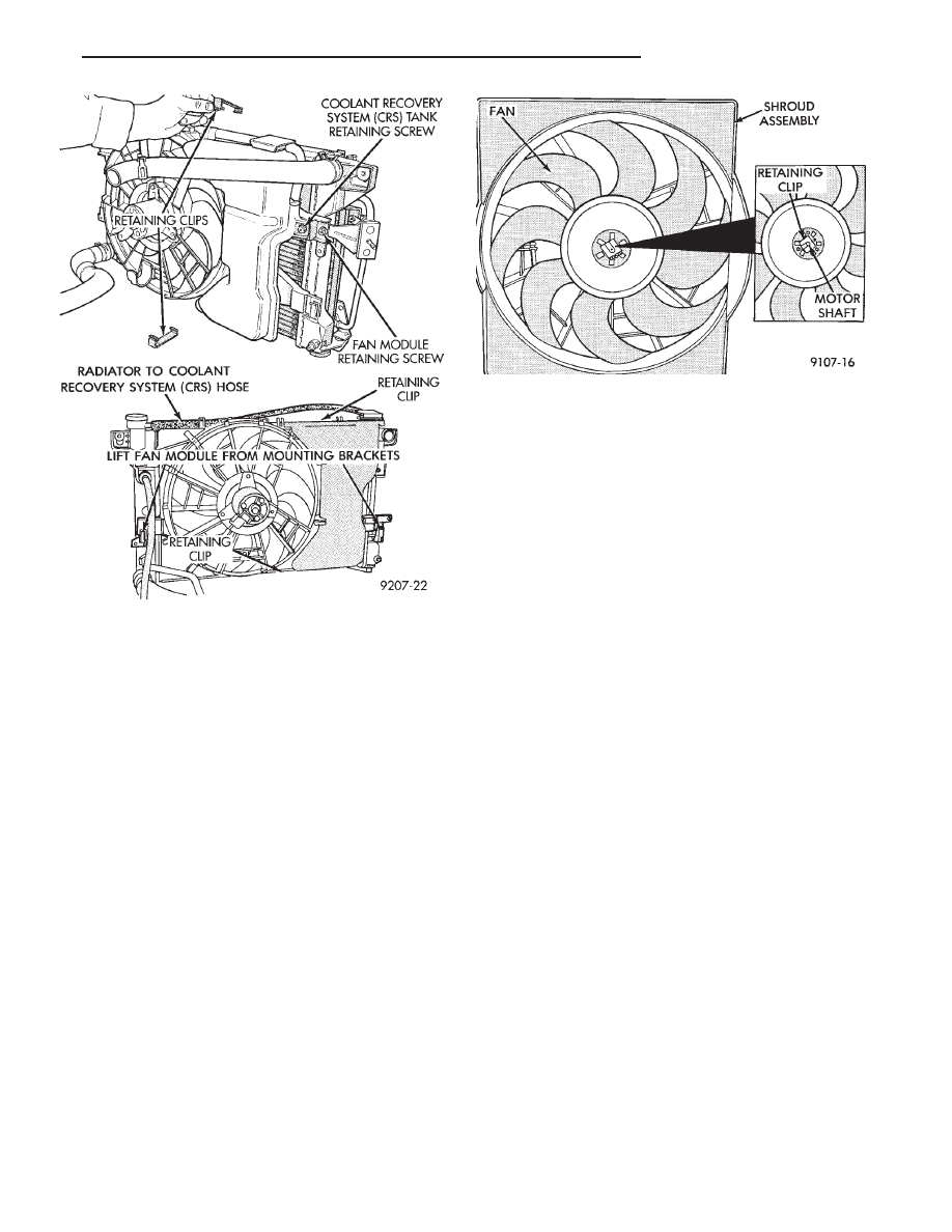
FANS
All models use electric motor driven cooling system
fans. The fan modules include a motor support which
may (depending on model) include a shroud. The
module is fastened to the radiator by screws with
U-nuts and retaining clips (Fig. 12).
All fan motors are one speed. Attempts to reduce
high temperature gauge reading by increasing en-
gine speed, at the same vehicle speed, can increase
high temperature.
SINGLE FAN
There are no repairs to be made to the fan. If the
fan is warped, cracked, or otherwise damaged, it
must be replaced with only the recommended part for
adequate strength, performance and safety (Fig. 13).
DUAL FAN MODULE—AC/AY BODY
The dual fan module (Fig. 11) is a combination of 2
fans mounted in a one piece shroud which are simul-
taneously activated. The dual fan system improves
engine cooling and air conditioning performance in hot
weather and severe driving conditions, while reducing
fan noise and power consumption.
REMOVAL
Disconnect electric motor lead. Remove fan module
to radiator fasteners and retaining clips. Remove as-
sembly from radiator support.
To remove fan from motor shaft, bench support the
motor and motor shaft, while removing the fan retain-
ing clip, so that the shaft and motor will not be
damaged by excessive force. Surface or burr re-
moval may be required to remove fan from motor
shaft. (Fig. 13). Do not permit the fan blades to touch
the bench.
INSTALLATION
Slide the fan on motor shaft. Support motor and
shaft as above while installing fan retaining clip.
Install assembly into pocket on lower radiator tank.
Attach retaining clips and fasteners to radiator tank.
Right side fastener is longer on A/C equipped
vehicles. Connect fan motor lead. For wiring dia-
grams of fan motor systems see Wiring Diagrams
Manual
RADIATOR FAN CONTROL—ALL EXCEPT V-6
ENGINE
Fan control is accomplished two ways. The fan al-
ways runs when the air conditioning compressor
clutch is engaged. In addition to this control, the fan is
turned on by the temperature of the coolant which is
sensed by the coolant temperature sensor which
Fig. 12 Servicing Fan Module
Fig. 13 Radiator Fan Retaining Clip—Typical
Ä
COOLING SYSTEM
7 - 21
sends the message to the Engine Controller. The En-
gine Controller turns on the fan through the fan re-
lay. See Wiring Diagrams Manual for circuity and
diagnostics provided.
Switching through the Engine Controller provides
fan control for the following conditions.
• The fan will not run during cranking until the en-
gine starts no matter what the coolant temperature
is.
• Fan will run when the air conditioning clutch is
engaged and low pressure cutout switch is closed.
• For 4 cylinder application the fan will run at ve-
hicle speeds above about 40 mph only if coolant tem-
perature reaches 110°C (230°F). It will turn off when
the temperature drops to 104°C (220°F). At speeds
below 40 mph the fan switches on at 102°C (215°F)
and off at 93°C (200°F).
• This is to help prevent steaming. The fan will run
only below 16°C (60°F) ambient. Between 38°C
(100°F) to 97°C (195°F) coolant temperature, at idle
and then only for three minutes.
RADIATOR FAN CONTROL—AC/AY BODY V-6
ONLY
For this application, fan control is accomplished
based on coolant temperature, and on A/C head pres-
sure. These vehicles receive the variable displace-
ment compressor. The fan will go on when;
• Coolant temperature reaches 102°C (215°F) and off
at 93.4°C (200°F) regardless of vehicle speed.
• When the head pressure reaches 1516.9 kPa (220
psi) and turn off when the pressure reaches 1103 kPa
(160 psi).
TEMPERATURE GAUGE INDICATION
At idle the temperature gauge will rise slowly to
about 5/8 gauge travel. The fan will come on and the
gauge will drop to about 1/2 gauge travel, this is nor-
mal.
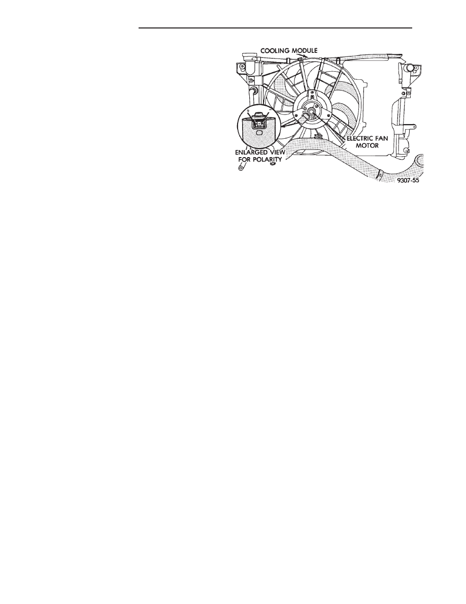
ELECTRIC FAN MOTOR
To check out the electric fan motor, disconnect the
fan motor wire connector and connect it with #14
gauge wires to a good 12-volt battery observing cor-
rect polarity per (Fig. 14). If the fan runs normally,
the motor is functioning properly. If not, replace fan
module using the removal and installation instruc-
tions contained in the Fan Section. If the motor is
noticeably overheated (i.e.; wire insulation melted,
motor charred) the system voltage may be too high.
Check charging system, see Group 8A, Battery/Start-
ing/Charging System Diagnostics.
ELECTRIC FAN MOTOR TEST
Equipment required
• Diagnostic Tool DRB II or equivalent
• Volt/Ohm Meter
• Wiring Diagram Manual
(1) Run the engine to normal operating tempera-
ture.
(2) Check wiring connector in C25, C9, and C26 for
proper engagement, see Wiring Diagram Manual
(3) Using a diagnostic tool, plugged into the diag-
nostic connector rearward of the battery, check the
On-Board Diagnostics (OBD) in the Engine Control-
ler for fault codes, see Group 14, Fuel Injection for
instructions.
(4) If fault code 88-12-35-55 is detected, proceed to
Step 5.
(5) With the ignition switch in the run position,
test for battery voltage (single pin connector) at the
fan relay. Voltage reading OK, proceed to Step 6a.
Voltage at 0-1 volt, proceed to Step 6b.
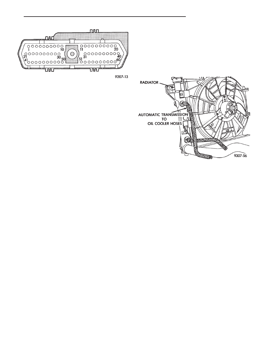
6(a) With the ignition off, disconnect the 60-way
connector from the Engine Controller (outboard of
battery) and return the ignition to the run position.
Test for battery voltage at cavity 31 of the 60-way
connector (Fig. 15). Voltage reading OK and female
terminal is not damaged, replace the Engine Control-
ler. Voltage reading 0, repair open or short in C27
circuit.
(b) With the ignition off, disconnect the 60-way
connector from the Engine Controller (outboard of
battery) and return the ignition to the run position.
Test for battery voltage at the single pin connector
at the fan relay. Voltage reading OK, replace the
Engine Controller. Voltage reading 0-1 volt, pro-
ceed to Step 7.
(7) With ignition in the run position, test for bat-
tery voltage at the wire (C27) in the 3-way connector
of the fan relay. Voltage reading OK, replace the fan
relay. Voltage reading 0, repair open or short in C27
circuit.
(8) Turn ignition off, connect the 60-way connector
at the Engine Controller and test the system.
Fig. 14 Electric Fan Motor—Typical
7 - 22
COOLING SYSTEM
Ä
FAN SHROUD
All vehicles have fan shrouds to improve fan air
flow efficiency. These fan shrouds cover less than full
radiator frontal area to prevent the shroud from re-
stricting air flow at high speeds.
The shroud supports the electric fan motor and fan.
For removal and installation see Radiator Section.
AUTOMATIC TRANSMISSION OIL COOLERS
Oil coolers are internal oil to coolant type, mounted
in the radiator left tank (Fig. 16). Rubber oil lines
feed the oil cooler and the automatic transmission.
Use only approved transmission oil cooler hose. Since
these are molded to fit space available, molded hoses
are recommended. Tighten Oil Cooler Hose Clamps
to 4 N
Im (35 in. lbs.).
Fig. 15 Engine Controller 60-Way Connector from
Terminal End
Fig. 16 Transmission Oil Cooler
Ä
COOLING SYSTEM
7 - 23
ACCESSORY DRIVE BELTS
INDEX
page
page
2.2/2.5L Engine Belts Remove/Install-Adjust
. . . . 24
3.0L Engine Belts Remove/Install and Adjust
. . . . 25
3.3/3.8L and Turbo III Engine Accessory Drive Belt
Remove and Install
. . . . . . . . . . . . . . . . . . . . . 26
General Information
. . . . . . . . . . . . . . . . . . . . . . . 24
GENERAL INFORMATION
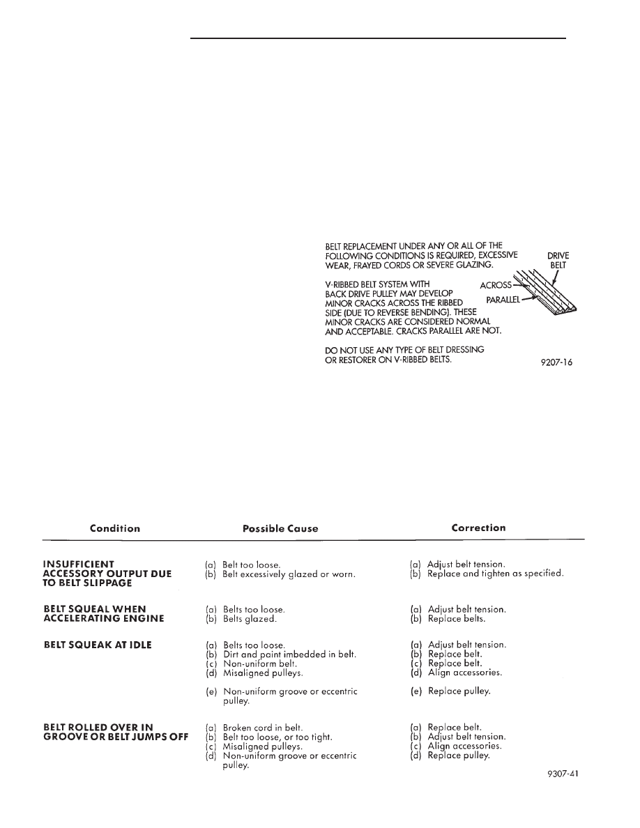
PROPER BELT TENSION
Satisfactory performance of the belt driven accesso-
ries depends on belt condition (Fig. 1) and proper belt
tension. Two tensioning methods are given in order
of preference:
• Belt tension gauge method.
• Torque equivalent method.
The belt tension gauge method is usually restricted
to use after the vehicle has been raised on a hoist
and the splash shield has been removed.
BELT TENSION GAUGE METHOD
Use belt tensioning Special Tool Kit C-4162 for:
• For conventional belts and Poly-V belts.
Adjust the belt tension for a New or Used belt as
prescribed in the Belt Tension Chart.
TORQUE EQUIVALENT METHOD
Adjustable accessory brackets provided with a
13mm (1/2 in.) square hole for a torque wrench can
use an equivalent torque value for belt adjustment.
Equivalent torque values for adjusting these acces-
sory drive belts are specified on the Belt Tension
Charts .
2.2/2.5L ENGINE BELTS REMOVE/INSTALL-
ADJUST
AIR CONDITIONING COMPRESSOR
(1) Loosen the idler bracket pivot screw A and
locking screws B (Fig. 2) to remove and install belt
and/or adjust belt tension.
ACCESSORY DRIVE BELTS DIAGNOSIS
Fig. 1 Drive Belt Inspection
7 - 24
COOLING SYSTEM
Ä
Нет комментариевНе стесняйтесь поделиться с нами вашим ценным мнением.
Текст