Chrysler Le Baron, Dodge Dynasty, Plymouth Acclaim. Manual — part 22

(1) Loosen fuel filler cap to release fuel tank pres-
sure.
(2) Disconnect injector wiring harness connector at
edge of throttle body (Fig. 4).
(3) Connect a jumper wire between terminal Num-
ber 1 of the injector harness and engine ground.
(4) Connect a jumper wire to the positive terminal
Number 2 of the injector harness and touch the bat-
tery positive post for no longer than 5 seconds.
This releases system pressure.
(5) Remove jumper wires.
(6) Continue fuel system service.
FUEL SYSTEM PRESSURE RELEASE
PROCEDURE—3.0L
(1) Disconnect the fuel rail electrical harness from
the engine harness. Refer to Group 8W, Wiring Dia-
grams.
(2) Connect one end of a jumper wire to the A142
circuit terminal of the fuel rail harness connector.
(3) Connect the other end of the jumper wire to a
12 volt power source.
(4) Connect one end of a jumper wire to a good
ground source.
(5) Momentarily ground one of the injectors by
connecting the other end of the jumper wire to an in-
jector terminal in the harness connector. Repeat pro-
cedure for 2 to 3 injectors.
FUEL PUMP ASSEMBLY
The fuel pump assembly consists of the fuel pump
and the reservoir body.
The reservoir body takes the place of an internal
fuel tank reservoir. The reservoir maintains fuel at
the pump inlet during all driving conditions, espe-
cially when the fuel level is low.
The system uses a positive displacement, gerotor
gear, immersible pump with a permanent magnet
electric motor (Fig. 5). The pump draws fuel through
a strainer and pushes it through the electric motor to
the outlet. The pump contains three check valves.
One valve relieves internal fuel pump pressure and
regulates maximum pump output. Another valve, in-
side the pump assembly in the fuel return circuit,
prevents fuel tank leakage if the line is damaged
during an accident. The third valve, in the pump out-
let, maintains pump pressure during engine off con-
ditions. The fuel pump relay provides voltage to the
fuel pump. All pumps have a maximum stall pres-
sure output of approximately 930 kPa (135 psi).
All front wheel drive car fuel systems, except
Turbo III and flexible fuel AA-body vehicles use the
same fuel pump. Turbo III and flexible fuel AA-Body
vehicles each use different fuel pumps although they
look similar to pumps used in other vehicles.
Release fuel system pressure before servicing the
fuel tank, fuel pump, fuel lines, fuel filter, or parts of
the fuel rail. Follow the Fuel System Pressure Re-
lease procedure to relieve fuel system pressure.
Fig. 2 Fuel Pressure Test Port—Typical
Fig. 3 Releasing Fuel Pressure—Engines With Test
Ports On Fuel Rail
Fig. 4 Injector Harness Connector—2.2L/2.5L TBI
Ä
FUEL SYSTEMS
14 - 5
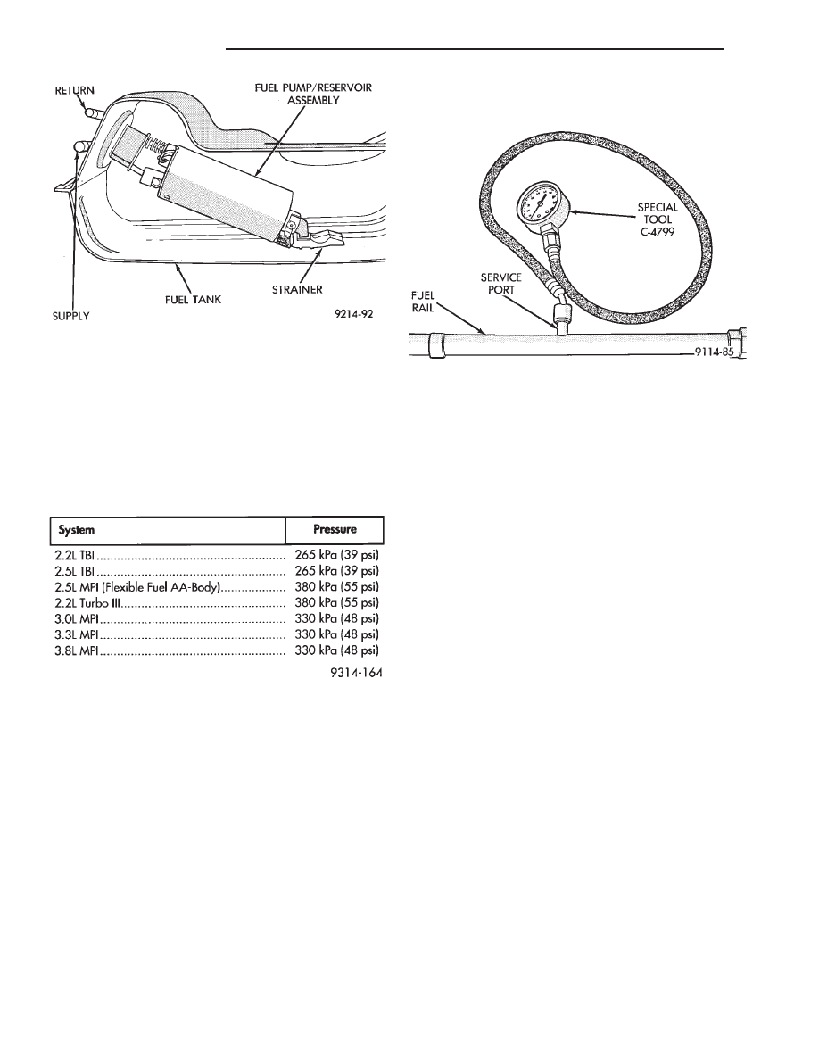
FUEL SYSTEM PRESSURE
Fuel system pressure is regulated at the fuel rail
or throttle body by a fuel pressure regulator. Refer to
the Fuel System Pressure Chart for pressure specifi-
cations. The chart reflects system pressure when the
pump is energized with the engine not running and
without vacuum applied to the pressure regulator.
FUEL PUMP PRESSURE TEST—ALL EXCEPT
2.2L/2.5L TBI AND 3.0L MPI
WARNING: RELEASE FUEL SYSTEM PRESSURE
BEFORE SERVICING FUEL SYSTEM COMPONENTS.
WHEN
SERVICING
FLEXIBLE
FUEL
VEHICLES,
WEAR METHANOL RESISTANT GLOVES AND EYE
PROTECTION AND AVOID BREATHING FUMES. DO
NOT ALLOW METHANOL/GASOLINE MIXTURES TO
CONTACT SKIN. SERVICE VEHICLES IN WELL VEN-
TILATED AREAS AND AVOID IGNITION SOURCES.
NEVER SMOKE WHILE SERVICING THE VEHICLE.
The specifications in the Fuel Pressure chart re-
flect system pressure with the vacuum hose removed
from the pressure regulator.
(1) Remove the vacuum hose from the pressure
regulator before checking fuel pressure.
(2) Release fuel system pressure. Refer to the Fuel
System Pressure Release procedure in this section.
(3) Connect Fuel Pressure Gauge C-4799 to service
port on fuel rail (Fig. 6).
CAUTION: When using the ASD Fuel System Test,
the Auto Shutdown (ASD) Relay remains energized
for either 7 minutes, until the test is stopped, or un-
til the ignition switch is turned to the Off position.
(4) Place the ignition key in the ON position. Us-
ing the DRBII scan tool, access ASD Fuel System
Test. The ASD Fuel System Test will activate the
fuel pump and pressurize the system.
If the gauge reads the specification listed in the
Fuel System Pressure chart, further testing is not re-
quired. If pressure is not correct, record the pressure
and remove gauge. Use the DRBII scan tool ASD
Fuel System Test to pressurize the system. Ensure
fuel does not leak from the fuel rail service valve. In-
stall protective cover on fuel rail service valve.
If pressure is below specifications, proceed to Fuel
System Pressure Below Specifications . If pres-
sure is above specifications, proceed to Fuel System
Pressure Above Specifications.
Fuel System Pressure Below Specifications
If the fuel pressure reading in step (4) was below
specifications, test the system according to the fol-
lowing procedure.
WARNING: RELEASE FUEL SYSTEM PRESSURE
BEFORE DISCONNECTING A FUEL SYSTEM HOSE
OR COMPONENT.
(a) Perform Fuel Pressure Release procedure.
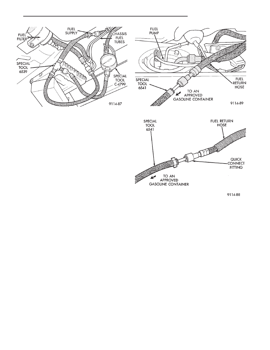
(b) Install Fuel Pressure Gauge C-4799 and Fuel
Pressure Test Adapter 6539 in the fuel supply line
between the fuel tank and fuel filter at the rear of
vehicle (Fig. 7).
(c) Using the DRBII scan tool, with the ignition
key in the ON position, repeat the ASD Fuel Sys-
tem Test.
Fig. 5 Fuel Pump—Typical
FUEL SYSTEM PRESSURE
Fig. 6 Fuel Pressure Testing—Engines With Service
Ports
14 - 6
FUEL SYSTEMS
Ä
• If pressure is at least 5 psi higher than reading
recorded in step (4), replace fuel filter.
• If no change is observed, gently squeeze the re-
turn hose. If fuel pressure increases, replace pressure
regulator. If gauge reading does not change while
squeezing the return hose, the problem is either a
plugged inlet strainer or defective fuel pump.
Fuel System Pressure Above Specifications
If the fuel pressure reading in step (4) was above
specifications, test the system according to the fol-
lowing procedure.
WARNING: RELEASE FUEL SYSTEM PRESSURE
BEFORE DISCONNECTING A FUEL SYSTEM HOSE
OR COMPONENT.
(a) Perform Fuel Pressure Release procedure.
(b) Remove the fuel return line hose from the
fuel pump at fuel tank.
(c) Connect Fuel Pressure Test Adapter 6541 to
the return line (Fig. 8). Place the other end of
adapter 6541 into an approved gasoline container
or a container approved for methanol/gasoline mix-
tures (minimum 2 gallon size). All return fuel will
flow into container.
(d) Using the DRBII scan tool, with the ignition
key in the ON position, repeat the ASD Fuel Sys-
tem Test.
• If pressure is now correct, replace fuel pump as-
sembly.
• If pressure is still above specifications, remove
fuel return hose from chassis fuel tubes (at engine).
Attach Fuel Pressure Test Connect Adapter 6541 to
the fuel return hose and place other end of hose in
clean container (Fig. 9). Repeat test. If pressure is
now correct, check for restricted fuel return line. If
no change is observed, replace fuel pressure regula-
tor.
FUEL PUMP PRESSURE TEST—2.2L/2.5L TBI and
3.0L MPI ENGINES
WARNING: RELEASE FUEL SYSTEM PRESSURE
BEFORE DISCONNECTING A FUEL SYSTEM HOSE
OR COMPONENT.
The specifications in the Fuel Pressure chart re-
flect system pressure with the vacuum hose removed
from the pressure regulator. Remove the vacuum line
from the pressure regulator on 3.0L engines before
testing fuel system pressure. The pressure regulators
on 2.2L/2.5L TBI engines are not vacuum assisted.
(1) Perform fuel system pressure release.
(2) Remove fuel supply hose quick connector from
the chassis lines (at the engine).
(3) Connect Fuel Pressure Gauge C-4799 to Fuel
Pressure Test Adapter 6539 (Fig. 10). Install the
adapter between fuel supply hose and chassis fuel
line assembly.
Fig. 7 Fuel Pressure Test
Fig. 8 Fuel Pressure Return Test
Fig. 9 Fuel Return Connection
Ä
FUEL SYSTEMS
14 - 7

CAUTION: When using the ASD Fuel System Test,
the Auto Shutdown (ASD) Relay remains energized
for either 7 minutes, until the test is stopped, or un-
til the ignition switch is turned to the Off position.
(4) Place the ignition key in the ON position. Us-
ing the DRBII scan tool, access ASD Fuel System
Test. The ASD Fuel System Test will activate the
fuel pump and pressurize the system.
If the gauge reads the pressure shown in the Fuel
System Pressure chart, further testing is not re-
quired. If pressure is not correct, record the pressure
and remove gauge.
If pressure is below specifications, proceed to Fuel
System Pressure Below Specifications. If pressure
is above specifications, proceed to Fuel System
Pressure Above Specifications.
Fuel System Pressure Below Specifications
If the fuel pressure reading in step (4) was below
specifications, test the system according to the fol-
lowing procedure.
WARNING: RELEASE FUEL SYSTEM PRESSURE
BEFORE DISCONNECTING A FUEL SYSTEM HOSE
OR COMPONENT.
(a) Perform Fuel Pressure Release procedure.
(b) Install Fuel Pressure Gauge C-4799 and Fuel
Pressure Adapter 6433 in the fuel supply line (Fig.
7) between the fuel tank and fuel filter.
(c) Using the DRBII scan tool, with the ignition
key in the ON position, repeat the ASD Fuel Sys-
tem Test.
• If pressure is at least 5 psi higher than reading
recorded in step (4), replace fuel filter.
• If no change is observed, gently the squeeze re-
turn hose. If fuel pressure increases, replace pressure
regulator. If the gauge reading does not change while
squeezing the return hose, the problem is either a
plugged inlet strainer or defective fuel pump.
Fuel System Pressure Above Specifications
If the fuel pressure reading in step (4) was above
specifications test the system according to the follow-
ing procedure.
WARNING: FUEL SYSTEM PRESSURE MUST BE
RELEASED BEFORE A FUEL SYSTEM HOSE OR
COMPONENT IS DISCONNECTED.
(a) Perform Fuel Pressure Release procedure.
(b) Install Fuel Pressure Gauge C-4799 and Fuel
Pressure Adapter 6433 in the fuel supply line be-
tween the fuel tank and fuel filter (Fig. 7).
(c) Remove the fuel return line hose from the
fuel pump at fuel tank. Connect Fuel Pressure Test
Adapter 6541 to the return line (Fig. 8). Place the
other end of adapter 6541 into an approved gaso-
line container or a container approved for gasoline/
methanol mixtures (minimum 2 gallon size). All
return fuel will flow into container.
(d) Using the DRBII scan tool, with the ignition
key in the ON position, repeat the ASD Fuel Sys-
tem Test.
• If pressure is now correct, replace fuel pump as-
sembly.
• If pressure is still above specifications, remove fuel
return hose from chassis fuel tubes (at engine). Attach
Fuel Pressure Test Connect Adapter 6541 to the fuel re-
turn hose and place other end of hose in clean approved
gasoline container or a container approved for metha-
nol/gasoline mixtures (Fig. 9). Repeat test. If pressure is
now correct, check for restricted fuel return line. If no
change is observed, replace fuel pressure regulator.
MECHANICAL MALFUNCTIONS
Mechanical malfunctions are more difficult to diag-
nose with this system. The powertrain control mod-
ule
(PCM)
compensates
for
some
mechanical
malfunctions. If engine performance problems are en-
countered, and no fault codes are displayed, the prob-
lem may be mechanical rather than electronic.
FUEL PUMP MODULE REMOVAL
WARNING: RELEASE FUEL SYSTEM PRESSURE
BEFORE SERVICING FUEL SYSTEM COMPONENTS.
WHEN
SERVICING
FLEXIBLE
FUEL
VEHICLES,
WEAR METHANOL RESISTANT GLOVES AND EYE
PROTECTION AND AVOID BREATHING FUMES. DO
NOT ALLOW METHANOL/GASOLINE MIXTURES TO
CONTACT SKIN. SERVICE VEHICLES IN WELL VEN-
TILATED AREAS AND AVOID IGNITION SOURCES.
NEVER SMOKE WHILE SERVICING THE VEHICLE.
Remove the fuel tank to service the fuel pump. Re-
fer to Fuel Tank Section for fuel tank removal.
(1) Using a hammer and a brass drift punch care-
fully tap lock ring counter clockwise to release pump
(Fig. 11).
Fig. 10 Fuel Pressure Gauge and Adapter
14 - 8
FUEL SYSTEMS
Ä
Нет комментариевНе стесняйтесь поделиться с нами вашим ценным мнением.
Текст