Chrysler Le Baron, Dodge Dynasty, Plymouth Acclaim. Manual — part 330
(3) Secure arm to pivot with attaching nut and
tighten 17 to 22 N
Im (155 to 195 in. lbs.) torque.
(4) Close head cover and remove pin from arm pin
hole.
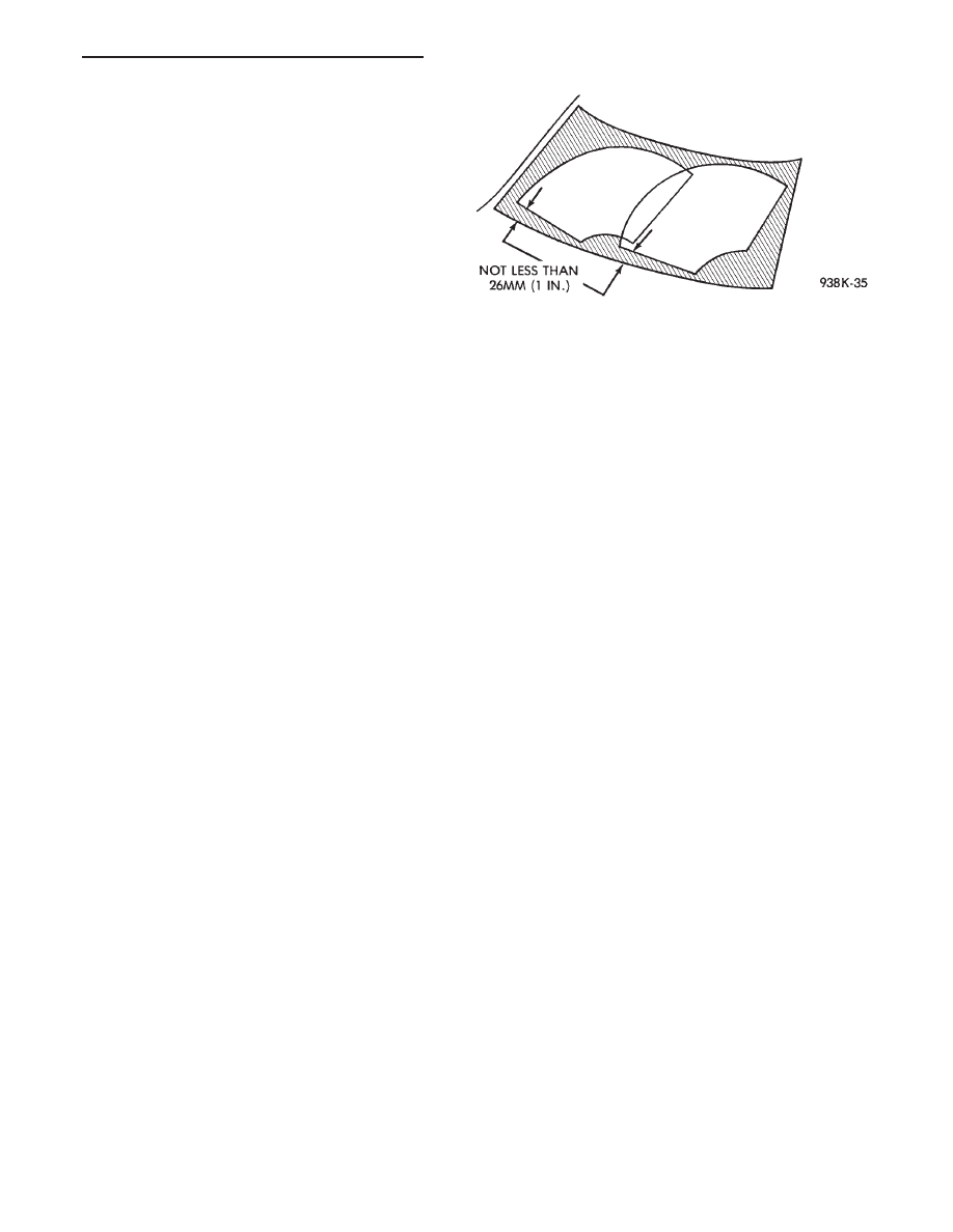
WIPER ARM ADJUSTMENT
FRONT ARM ADJUSTMENT
(1) Cycle the wiper motor into the PARK position.
(2) Check the tips of the blades in blackout area.
From the bottom edge of the windshield to the blade
should be no closer than 25 mm (1 inch) (Fig. 8).
(3) Operate the wipers if the requirements are not
met, check linkage and pivot assembly for worn
parts.
REAR ARM ADJUSTMENT
With the motor in the park position, mount the
arm on the motor shaft. Choose a serration engage-
ment that positions the blade, parallel with the bot-
tom edge of the liftgate glass.
WINDSHIELD WIPER MOTOR AND LINKAGE ASSEMBLY SERVICE PROCEDURES
INDEX
page
page
Front Wiper Motor Assembly—AG and AJ Bodies
. 6
Rear Wiper Motor Assembly—AG Body
. . . . . . . . 8
Rear Wiper Motor—AG Body Test
. . . . . . . . . . . . 6
Wiper Motor and Linkage Assembly—AA, AC, AY
Bodies
. . . . . . . . . . . . . . . . . . . . . . . . . . . . . . . . 8
Wiper Motor and Linkage Assembly—AP Body
. . 10
Wiper Motor System Test Procedures
. . . . . . . . . . 3
WIPER MOTOR SYSTEM TEST PROCEDURES
WARNING: ON VEHICLES EQUIPPED WITH AIR-
BAG, SEE GROUP 8M, RESTRAINT SYSTEMS FOR
STEERING WHEEL OR COLUMN REMOVAL PROCE-
DURES.
Whenever a wiper motor malfunction occurs, first
verify that the wiper motor wire harness is properly
connected to all connectors before starting normal di-
agnosis and repair procedures. Refer to Wiper Motor
Diagnosis Chart (Fig. 9).
The following is a list of general wiper motor sys-
tem problems, the tests that are to be performed to
locate the faulty part, and the corrective action to be
taken. These tests will cover both two speed and in-
termittent wipe functions.
TWO SPEED MOTOR FUNCTION TESTS
CONDITION: MOTOR WILL NOT RUN IN ANY
SWITCH POSITION
PROCEDURE
(1) Check for a blown fuse in the fuse block.
(a) If fuse is good, proceed to step 2.
(b) If fuse is defective, replace and check motor
operation in all switch positions.
(c) If motor is still inoperative and the fuse does
not blow, proceed to step 2.
(d) If replacement fuse blows, proceed to step 5.
(2) Place switch in LOW speed position.
(3) Listen to motor. If you cannot hear it running,
proceed to Step 4. If you hear it running, check motor
output shaft. If output shaft is not turning, replace
motor assembly. If it is turning, drive link to output
shaft or linkage is not properly connected. Replace
worn parts and/or properly connect drive link to the
motor output shaft.
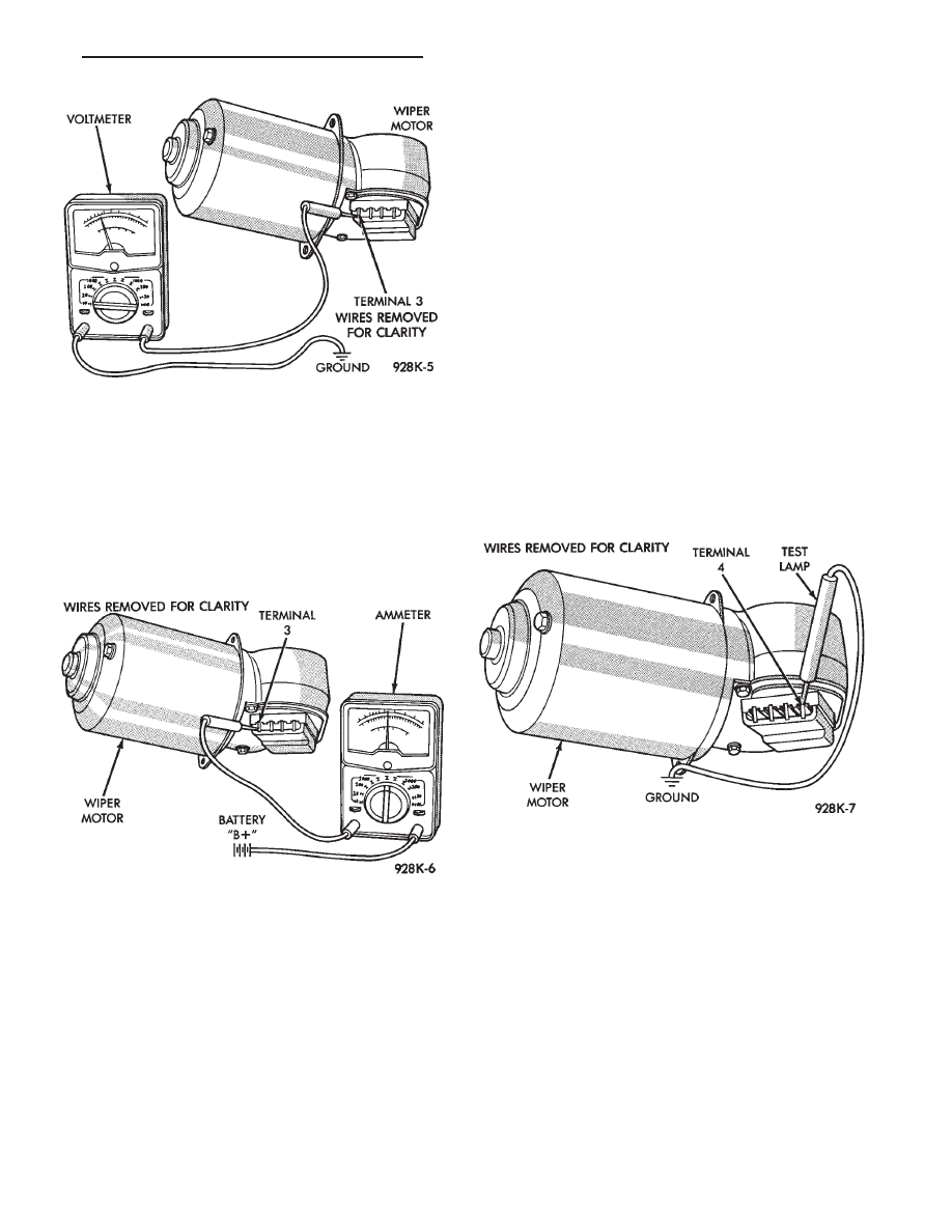
(4) Connect a voltmeter between motor terminal 3
and ground strap (Fig. 10). If there is no voltage or very
little voltage (less than one volt) present, move nega-
tive test lead from the ground strap to negative battery
terminal.
(a) If an increase in voltage is noticed, the problem
is a bad ground circuit. Make sure the motor mount-
ing is free of paint and that nuts or bolts are tight.
(b) If there is still no indication of voltage, the
problem is an open circuit in the wiring harness or
wiper switch.
(c) If no more than 3 volts increase in voltage is
observed, the problem is a faulty motor assembly.
(5) Disconnect motor wiring connector and replace
fuse.
(a) If fuse does not blow, motor is defective.
(b) If fuse blows, switch or wiring is at fault.
Fig. 8 Windshield Wiper Arm Adjustment
Ä
WINDSHIELD WIPER AND WASHER SYSTEMS
8K - 3
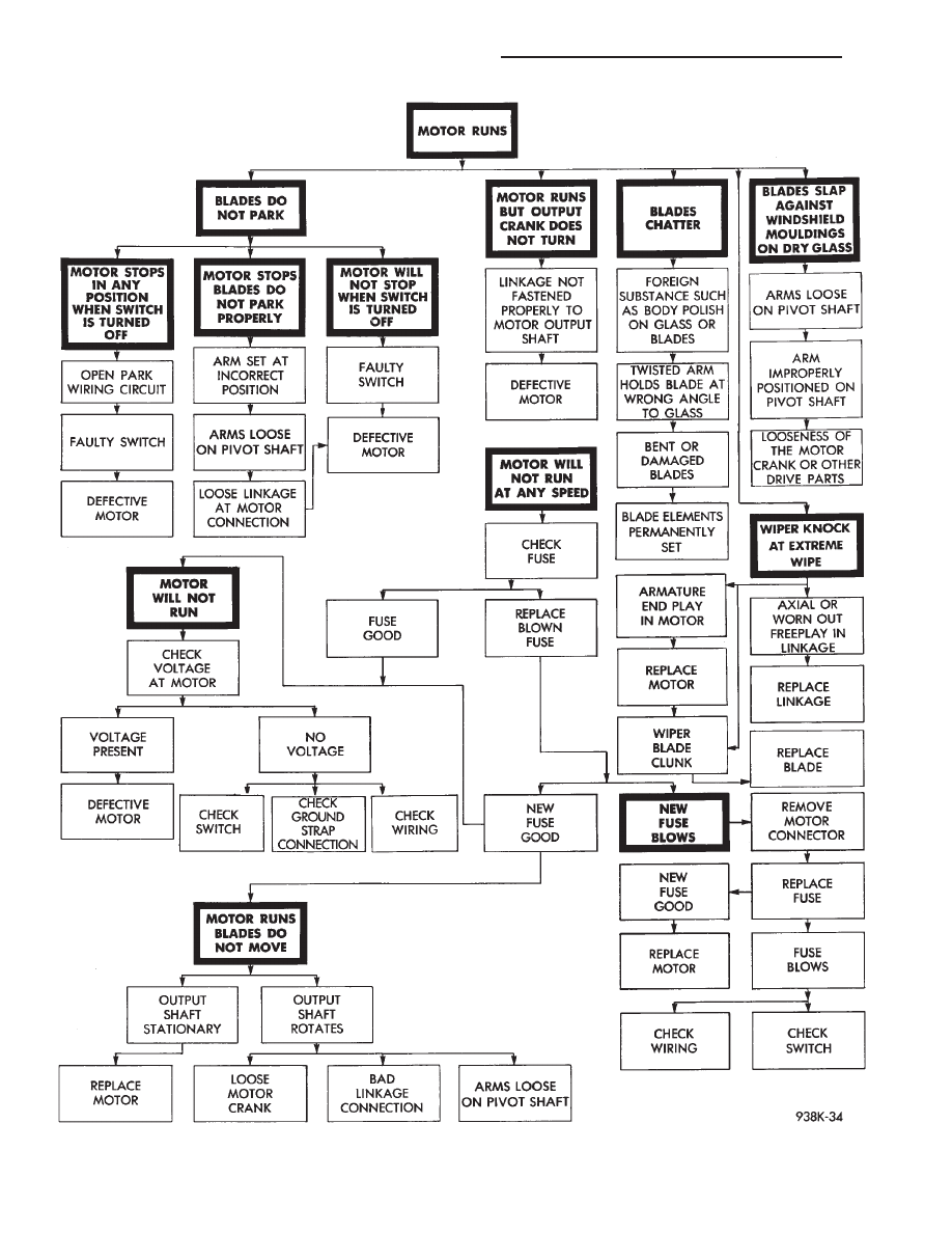
Fig. 9 Windshield Wiper Motor Diagnosis
8K - 4
WINDSHIELD WIPER AND WASHER SYSTEMS
Ä
CONDITION: MOTOR RUNS SLOWLY AT ALL
SPEEDS
PROCEDURE
(1) Disconnect wiring harness connector at motor.
Remove wiper arms and blades. Connect an ammeter
between battery (B+) and terminal 3 on motor (Fig.
11).
(a) If motor runs and average ammeter reading
is more than 6 amps, proceed to step 2.
(b) If motor runs and average ammeter reading
is less than 6 amps, proceed to step 3.
(2) Check to see if wiper linkage or pivots are
binding or caught. Disconnect drive link from motor.
(a) If motor now runs and draws less than 3
amps, repair linkage system.
(b) If motor continues to draw more than 3 amps,
replace motor assembly.
(3) Check motor wiring harness for shorting be-
tween high and low speed wires as follows:
(a) Connect a voltmeter or test lamp to motor
ground strap.
(b) Set wiper switch to LOW position.
(c) Connect other lead of voltmeter to terminal 4
of the wiring harness.
(d) If voltage is present, there is a short in the
wiring or wiper switch. If no voltage is present pro-
ceed to step e.
(e) Set wiper switch to HIGH position.
(f) Move voltmeter lead from terminal 4 to termi-
nal 3 of the wiring harness.
(g) If voltage is present, there is a short in the
wiring or wiper switch.
CONDITION: MOTOR WILL RUN AT HIGH
SPEED, BUT NOT AT LOW SPEED. MOTOR
WILL RUN AT LOW SPEED, BUT NOT AT HIGH
SPEED
PROCEDURE
(1) If motor will not run on high speed, put switch
in HIGH position and connect a test lamp between
motor Terminal 4 and ground (Fig. 12).
(2) If motor will not run on low speed, put switch
in LOW position and connect a test lamp between
motor Terminal 3 and ground.
(3) If test lamp does not light at motor terminal,
there is an open in wiring or switch. If test lamp
lights at motor terminal, replace motor assembly.
CONDITION: MOTOR WILL KEEP RUNNING
WITH SWITCH IN OFF POSITION
PROCEDURE
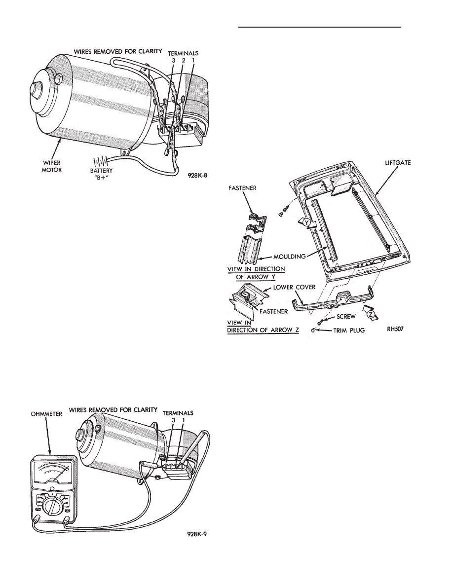
Remove wiring harness. Connect jumper from Ter-
minal 1 to Terminal 3 of wiper motor (Fig. 13). Con-
nect second jumper from Terminal 2 to battery (B+).
If motor runs to PARK position and stops, wiper
switch is faulty. If motor keeps running and does not
park, replace motor assembly.
Fig. 10 Voltmeter Between Terminal 3 and Ground
Fig. 11 Ammeter Between Terminal 3 and Battery
Fig. 12 Test Lamp Between Terminal 4 and Ground
Ä
WINDSHIELD WIPER AND WASHER SYSTEMS
8K - 5
CONDITION: MOTOR WILL STOP WHEREVER
IT IS, WHEN COLUMN SWITCH IS PUT IN OFF
POSITION. THE WIPERS DO NOT CONTINUE
RUNNING TO PARK POSITION
PROCEDURE
(1) Remove motor wiring connector and clean ter-
minals. Reconnect connector and test motor.If prob-
lem persists, proceed to Step 2.
(2) Set wiper switch to OFF position. Disconnect
motor wiring connector. Connect a voltmeter or test
lamp to the motor ground strap. Connect the other
lead to terminal 2 of wiring connector.
(a) If voltage is not present, check for an open
circuit in the wiring harness or wiper control
switch.
(b) If voltage is present, proceed to step 3.
(3) Connect an ohmmeter or continuity tester be-
tween terminals 3 and 1 (Fig. 14).
(a) If there is continuity between these termi-
nals, the problem is a defective motor.
(b) If there is no continuity, the problem is an
open circuit in the wiper control switch or wiring
harness.
REAR WIPER MOTOR—AG BODY TEST
The following test is used in order to locate and
then repair liftgate wiper motor defects. Refer to
Group 8W, Wiring Diagrams for liftgate wiper motor
wiring schematic.
(1) Remove lower cover on liftgate (Fig. 15).
(2) Disconnect feed connector from wiper motor.
(3) With ignition switch in ON position, check for
battery voltage at blue wire.
(4) With ignition switch in ON position and wiper
switch ON, check for battery voltage at blue and
brown wire. If battery voltage is not present in steps
3 and 4, check fuse, liftgate wiper switch and wiring.
(5) With ignition switch in ON position, and wiper
switch in OFF position, check for battery voltage be-
tween blue and brown wires. If battery voltage is not
present, check ground wire to liftgate switch.
(6) If battery voltage is present in steps 3 and 4,
replace motor.
FRONT WIPER MOTOR ASSEMBLY—AG and AJ
BODIES
REMOVAL
(1) Park system.
(2) Open the hood assembly.
(3) Remove wiper arms and blades, disconnect
hoses from tee connector (Fig. 16).
Fig. 13 One Jumper Wire Between Terminal 1 and 3.
One Jumper Wire Between Terminal 2 and Battery
positive
Fig. 14 Ohmmeter Between Terminals 3 and 1
Fig. 15 Liftgate Lower Cover
8K - 6
WINDSHIELD WIPER AND WASHER SYSTEMS
Ä
Нет комментариевНе стесняйтесь поделиться с нами вашим ценным мнением.
Текст