Chrysler Le Baron, Dodge Dynasty, Plymouth Acclaim. Manual — part 5
Ä
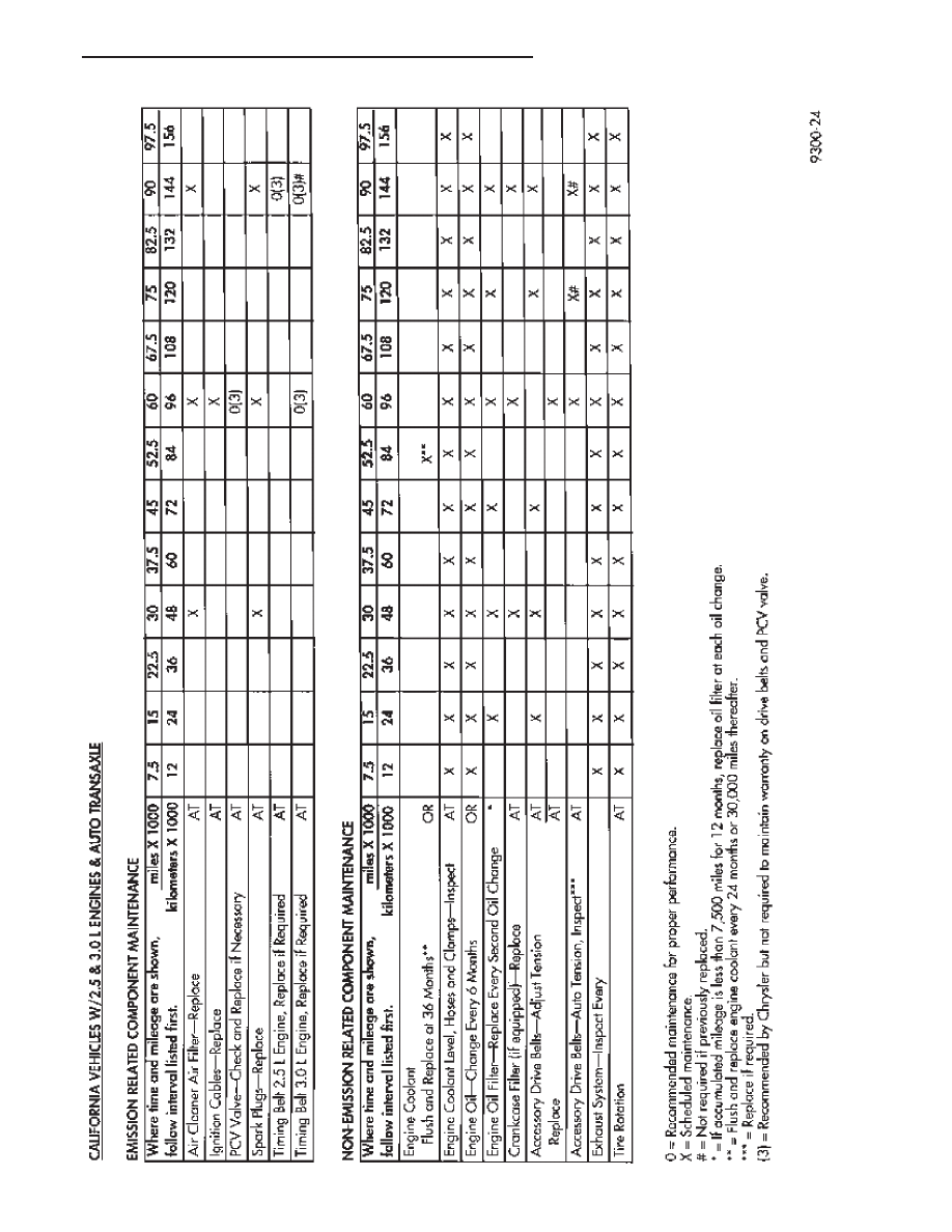
LUBRICATION AND MAINTENANCE
0 - 3
LUBRICANTS AND GREASES
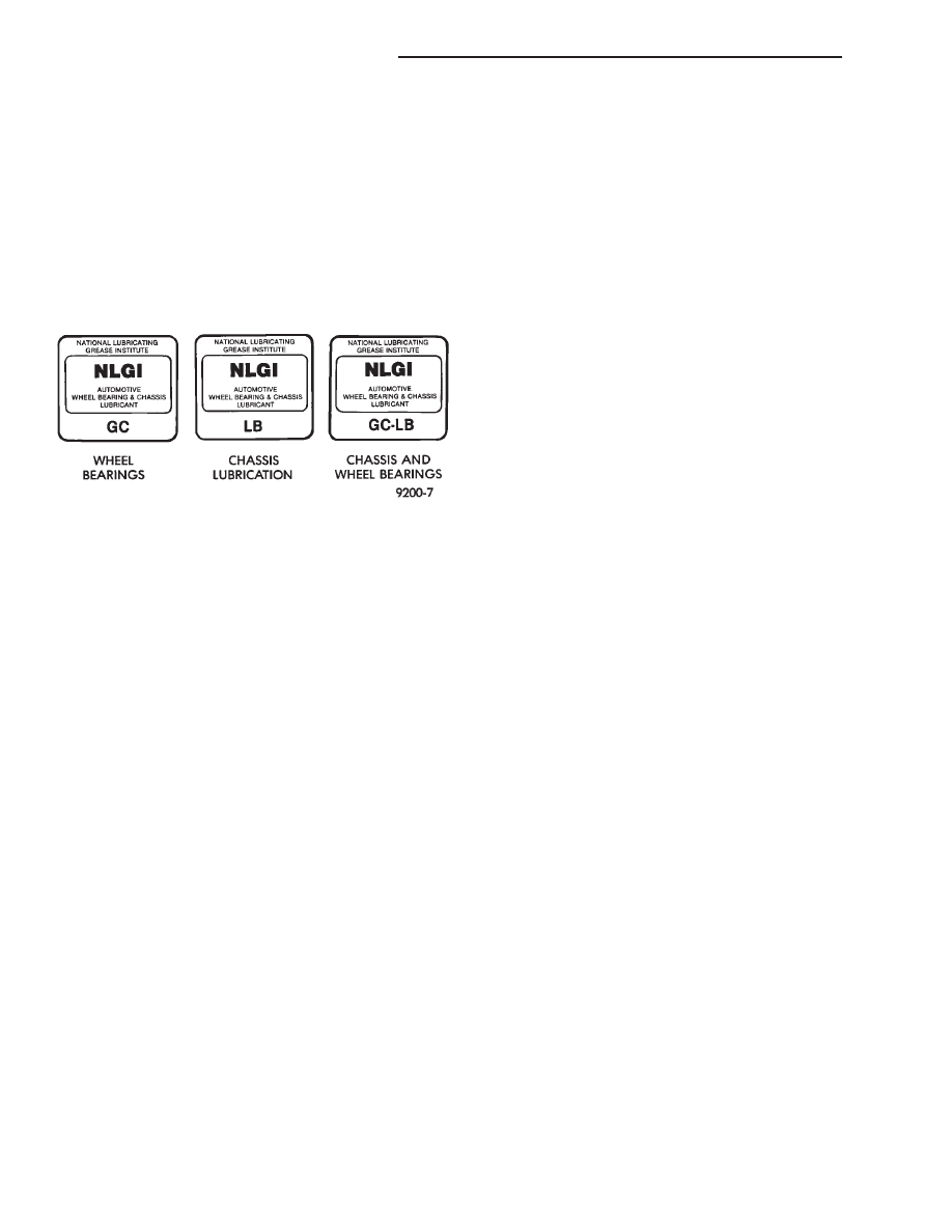
Lubricating grease is rated for quality and usage
by the NLGI. All approved products have the NLGI
symbol on the label.
At the bottom NLGI symbol is the usage and qual-
ity identification letters. Wheel bearing lubricant is
identified by the letter ‘‘G’’. Chassis lubricant is iden-
tified by the letter ‘‘L’’. The letter following the us-
age letter indicates the quality of the lubricant. The
following symbols indicate the highest quality.
FLUID CAPACITIES
Fuel Tank
AP,AG and AJ. . . . . . . . . ..53 L (14 gal.)
AA,AC and AY. . . . . . . . . .60 L (16 gal.)
AA-Flexible Fuel . . . . . . . . ..68 L (18 gal.)
Engine Oil
All. . . . . . . . . . . . . . .3.8 L (4.5 qts.)
Cooling System
2.2L . . . . . . . . . . . . . ..8.5 L (9.0 qts.)
2.5L . . . . . . . . . . . . . ..8.5 L (9.0 qts.)
3.0L . . . . . . . . . . . . . ..9.0 L (9.5 qts.)
3.3L . . . . . . . . . . . . . ..9.0 L (9.5 qts.)
3.8L . . . . . . . . . . . . . ..9.0 L (9.5 qts.)
Includes heater and coolant recovery bottle
Automatic Transaxle
Estimated Service Fill
ALL . . . . . . . . . . . . . ..3.8 L (4.0 qts.)
Overhaul Fill Capacity with Torque Converter
Empty
3-speed Fleet . . . . . . . . . ...8.7 L (9.2 qts.)
3-speed . . . . . . . . . . . . .8.2 L (8.8 qts.)
4-speed Electronic . . . . . . . . 9.4L (9.9 qts.)
Manual Transaxle
All . . . . . . . . . . . . . . ..9.4L (9.9 qts.)
Fill to bottom of fill hole.
Power Steering
All . . . . . . . . . . . . . . ...75L (1.5 pts.)
PARTS REQUIRING NO LUBRICATION
Many components on a Chrysler Corporation vehi-
cle require no periodic maintenance. Some compo-
nents are sealed and permanently lubricated. Rubber
bushings can deteriorate or limit damping ability if
lubricated. The following list of components require
no lubrication:
• Air Pump
• Generator Bushings
• Drive Belts
• Drive Belt Idler/Tensioner Pulley
• Front Wheel Bearings
• Rubber Bushings
• Starter Bearings/Bushings
• Suspension Strut Bearings
• Throttle Control Cable
• Throttle Linkage
• Water Pump Bearings
JUMP STARTING PROCEDURE
WARNING: REVIEW ALL SAFETY PRECAUTIONS
AND WARNINGS IN GROUP 8A, BATTERY/START-
ING/CHARGING SYSTEMS DIAGNOSTICS.
DO NOT JUMP START A FROZEN BATTERY, PER-
SONAL INJURY CAN RESULT.
DO NOT JUMP START WHEN BATTERY INDICA-
TOR DOT IS YELLOW OR BRIGHT COLOR.
DO NOT ALLOW JUMPER CABLE CLAMPS TO
TOUCH EACH OTHER WHEN CONNECTED TO A
BOOSTER SOURCE.
DO NOT USE OPEN FLAME NEAR BATTERY.
REMOVE METALLIC JEWELRY WORN ON HANDS
OR WRISTS TO AVOID INJURY BY ACCIDENTAL
ARCHING OF BATTERY CURRENT.
WHEN USING A HIGH OUTPUT BOOSTING DE-
VICE, DO NOT ALLOW BATTERY VOLTAGE TO EX-
CEED
16
VOLTS.
REFER
TO
INSTRUCTIONS
PROVIDED WITH DEVICE BEING USED.
CAUTION:
When
using
another
vehicle
as
a
booster, do not allow vehicles to touch. Electrical
systems can be damaged on either vehicle.
TO JUMP START A DISABLED VEHICLE:
(1) Raise hood on disabled vehicle and visually in-
spect engine compartment for:
• Battery cable clamp condition, clean if necessary.
• Frozen battery.
• Yellow or bright color test indicator, if equipped.
• Low battery fluid level.
• Generator drive belt condition and tension.
• Fuel fumes or leakage, correct if necessary.
CAUTION: If the cause of starting problem on dis-
abled vehicle is severe, damage to booster vehicle
charging system can result.
(2) When using another vehicle as a booster
source, turn off all accessories, place gear selector in
park or neutral, set park brake and operate engine
at 1200 rpm.
NLGI SYMBOL
0 - 4
LUBRICATION AND MAINTENANCE
Ä
(3) On disabled vehicle, place gear selector in park
or neutral and set park brake. Turn off all accesso-
ries.
(4) Connect jumper cables to booster battery. RED
clamp to positive terminal (+). BLACK clamp to
negative terminal (-). DO NOT allow clamps at oppo-
site end of cables to touch, electrical arc will result
(Fig. 1). Review all warnings in this procedure.
(5) On disabled vehicle, connect RED jumper cable
clamp to positive (+) terminal. Connect BLACK
jumper cable clamp to engine ground as close to the
ground cable attaching point as possible (Fig. 1).
CAUTION: Do not crank starter motor on disabled
vehicle for more than 15 seconds, starter will over-
heat and could fail.
(6) Allow battery in disabled vehicle to charge to
at least 12.4 volts (75% charge) before attempting to
start engine. If engine does not start within 15 sec-
onds, stop cranking engine and allow starter to cool
(15 min.), before cranking again.
DISCONNECT CABLE CLAMPS AS FOLLOWS:
• Disconnect BLACK cable clamp from engine
ground on disabled vehicle.
• When using a Booster vehicle, disconnect BLACK
cable clamp from battery negative terminal. Discon-
nect RED cable clamp from battery positive terminal.
• Disconnect RED cable clamp from battery positive
terminal on disabled vehicle.
HOISTING RECOMMENDATIONS
Refer to Owner’s Manual provided with vehicle for
proper emergency jacking procedures.
WARNING: THE HOISTING AND JACK LIFTING
POINTS PROVIDED ARE FOR A COMPLETE VEHI-
CLE. WHEN THE ENGINE OR REAR SUSPENSION
IS REMOVED FROM A VEHICLE, THE CENTER OF
GRAVITY IS ALTERED MAKING SOME HOISTING
CONDITIONS UNSTABLE. PROPERLY SUPPORT OR
SECURE VEHICLE TO HOISTING DEVICE WHEN
THESE CONDITIONS EXIST.
TO HOIST OR JACK VEHICLE SEE FIG. 2
THROUGH 7:
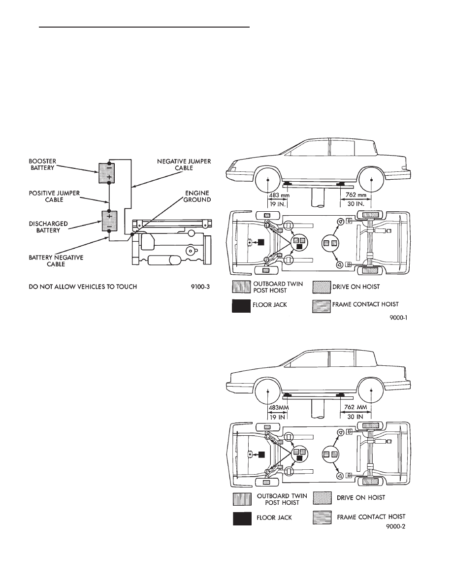
Fig. 1 Jumper Cable Clamp Connections
Fig. 2 Hoisting and Jacking Points—AY Body
Fig. 3 Hoisting and Jacking Points—AC Body
Ä
LUBRICATION AND MAINTENANCE
0 - 5
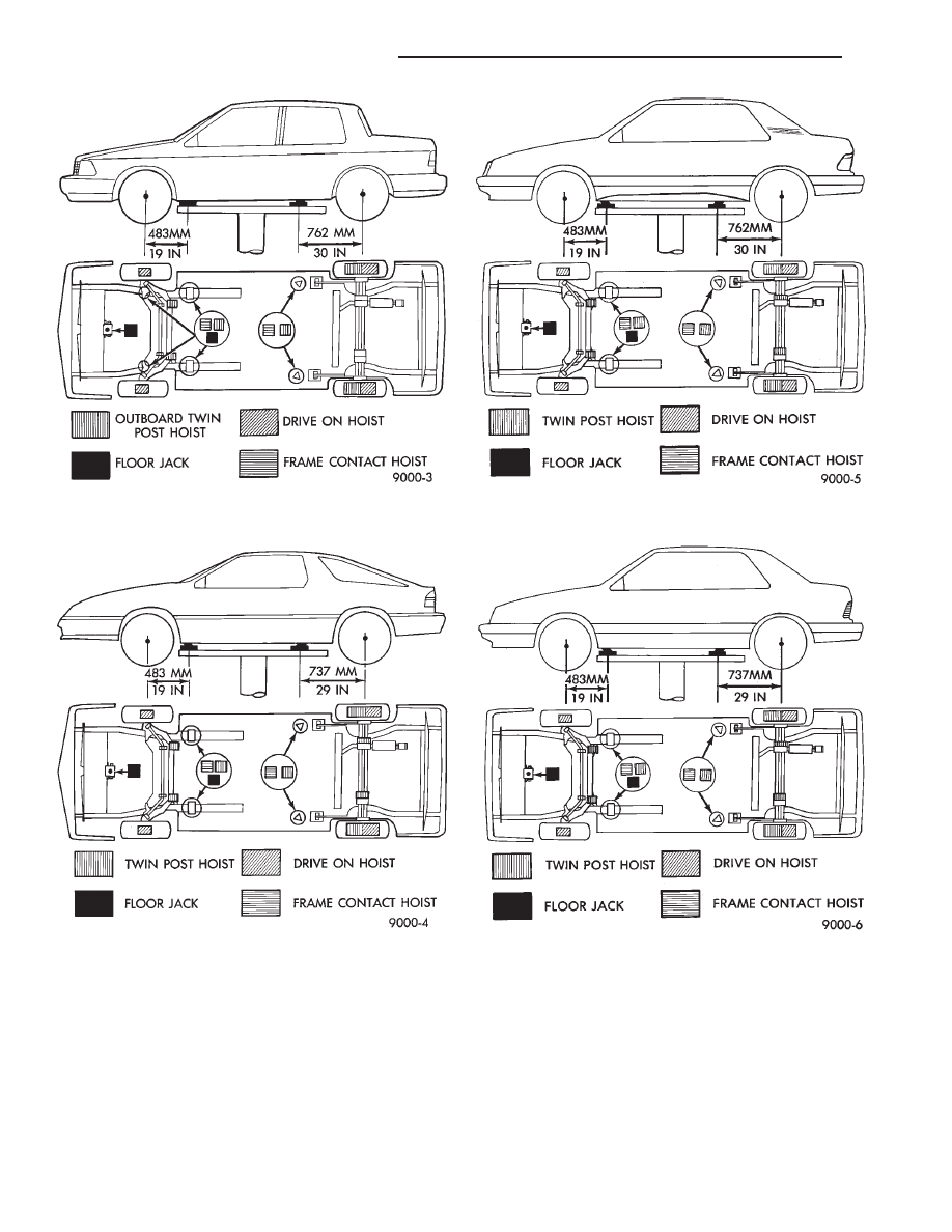
Fig. 4 Hoisting and Jacking Points—AA Body
Fig. 5 Hoisting and Jacking Points—AG Body
Fig. 6 Hoisting and Jacking Points—AJ Body
Fig. 7 Hoisting and Jacking Points—AP Body
0 - 6
LUBRICATION AND MAINTENANCE
Ä
Нет комментариевНе стесняйтесь поделиться с нами вашим ценным мнением.
Текст