Chrysler Le Baron, Dodge Dynasty, Plymouth Acclaim. Manual — part 14
CAUTION: When using the ASD Fuel System Test,
the Auto Shutdown (ASD) relay will remain ener-
gized for 7 minutes or until the ignition switch is
turned to the OFF position, or Stop All Test is se-
lected.
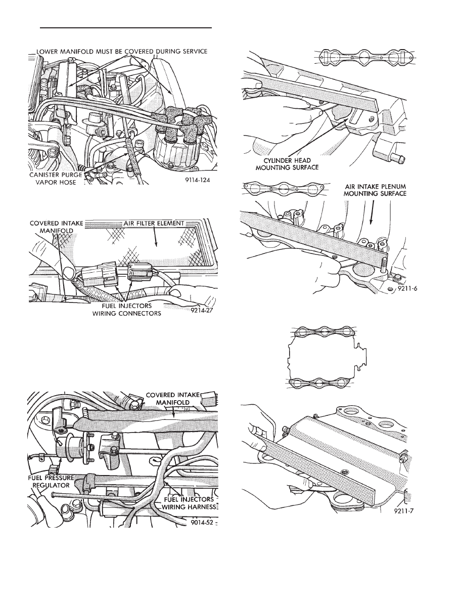
Fig. 13 Check Intake (Cross) Manifold Mounting
Surface
Fig. 14 Check Intake Plenum Mounting Surfaces
Fig. 10 Vacuum Connections for Fuel Rail and Fuel
Pressure Regulator
Fig. 11 Fuel Injector Wiring Harness
Fig. 12 Fuel Pressure Regulator to Fuel Rail
Assembly
Ä
EXHAUST SYSTEM AND INTAKE MANIFOLD
11 - 17
EXHAUST MANIFOLDS
REMOVAL
(1) Raise vehicle and disconnect exhaust pipe from
rear (cowl side) exhaust manifold at articulated joint.
(2) Disconnect Oxygen Sensor lead wire at the rear
exhaust manifold (Fig. 18).
(3) Remove bolts attaching cross-over pipe to man-
ifold (Figs. 2 and 19).
(4) Remove nuts attaching rear manifold to cylin-
der head and remove manifold.
(5) Lower vehicle and remove screws attaching
front heat shield to front manifold (Fig. 2).
(6) Remove bolts fastening crossover pipe to front
exhaust manifold and nuts fastening manifold to cyl-
inder head. Remove assemblies.
INSPECTION
Inspect exhaust manifolds for damage or cracks
and check distortion of the cylinder head mounting
surface and exhaust crossover mounting surface with
a straightedge and thickness gauge (Fig. 20).
INSTALLATION
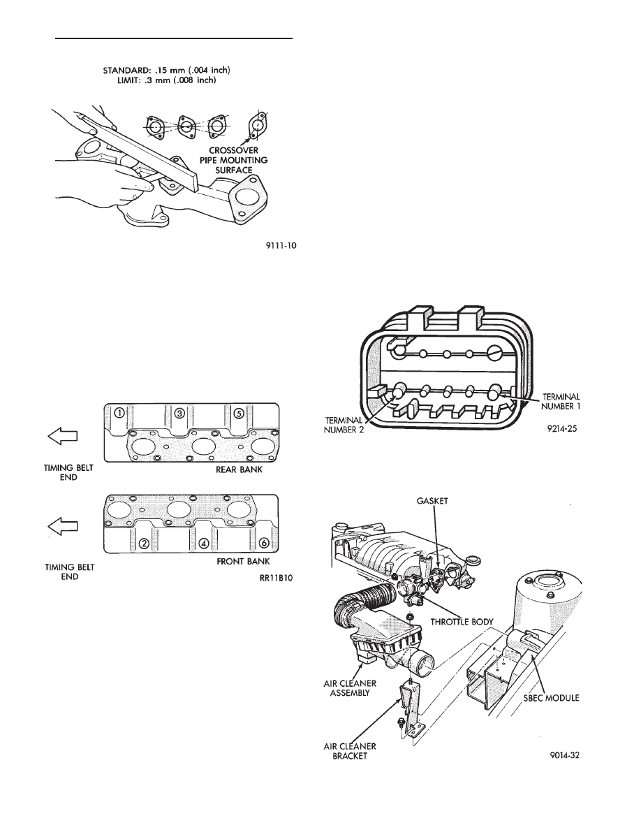
Install the gaskets with the numbers 1-3-5 em-
bossed on the top on the rear bank and those with
numbers 2-4-6 on the front (Radiator side) bank (Fig.
21).
(1) Install rear exhaust manifold and tighten at-
taching nuts to 20 N
Im (175 in. lbs.).
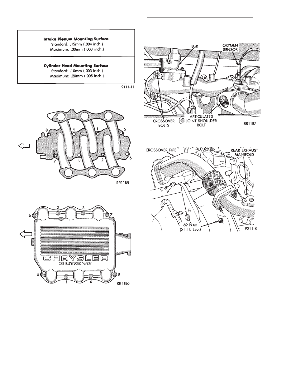
Fig. 15 Intake Plenum and Cylinder Head Mounting
Surface Specifications
Fig. 16 Nut Tightening Sequence for Intake (Cross)
Manifold
Fig. 17 Intake Plenum Tightening Sequence
Fig. 18 Separate Articulated Joint, Disconnect
Oxygen Sensor Wire
Fig. 19 Crossover Pipe
11 - 18
EXHAUST SYSTEM AND INTAKE MANIFOLD
Ä
(2) Attach exhaust pipe to exhaust manifold and
tighten shoulder bolt to 28 N
Im (250 in. lbs.)
(3) Attach crossover pipe to exhaust manifold and
tighten bolt to 69 N
Im (51 ft. lbs.)
(4) Connect heated oxygen sensor lead (Fig. 18).
(5) Install front exhaust manifold and attach ex-
haust crossover.
(6) Install front manifold heat shield and tighten
attaching screws to 15 N
Im (130 in. lbs.) (Fig. 2).
INTAKE/EXHAUST MANIFOLD SERVICE—3.3/3.8L
ENGINES
INTAKE MANIFOLD
REMOVAL
(1) Perform fuel system pressure release procedure,
Before attempting any repairs.
(2) Disconnect negative battery cable. Drain cool-
ing system. Refer to Cooling System, Group 7.
FUEL SYSTEM PRESSURE RELEASE PROCE-
DURE
The MPI fuel system is under a constant pressure
of about 330 kPa (48 psi). Before servicing the fuel
pump, fuel lines, fuel filter, throttle body or fuel
injector, the fuel system pressure must be released.
(a) Loosen fuel filler cap to release fuel tank pres-
sure.
(b) Disconnect injector wiring harness from engine
harness.
(c) Connect a jumper wire to ground terminal Num-
ber 1 of the injector harness (Fig. 1) to engine ground.
(d) Connect a jumper wire to the positive terminal
Number 2 of the injector harness (Fig. 1) and touch
the battery positive post for no longer than 5 seconds.
This releases system pressure.
(e) Remove jumper wires.
(f) Continue fuel system service.
(3) Remove air cleaner to throttle body hose assem-
bly (Fig. 2).
Fig. 20 Check Exhaust Manifold Mounting Surface
Fig. 21 Identify Exhaust Manifold Gaskets
Fig. 1 Injector Harness Connectors
Fig. 2 Throttle Body Assembly—3.3/3.8L Engines
Ä
EXHAUST SYSTEM AND INTAKE MANIFOLD
11 - 19
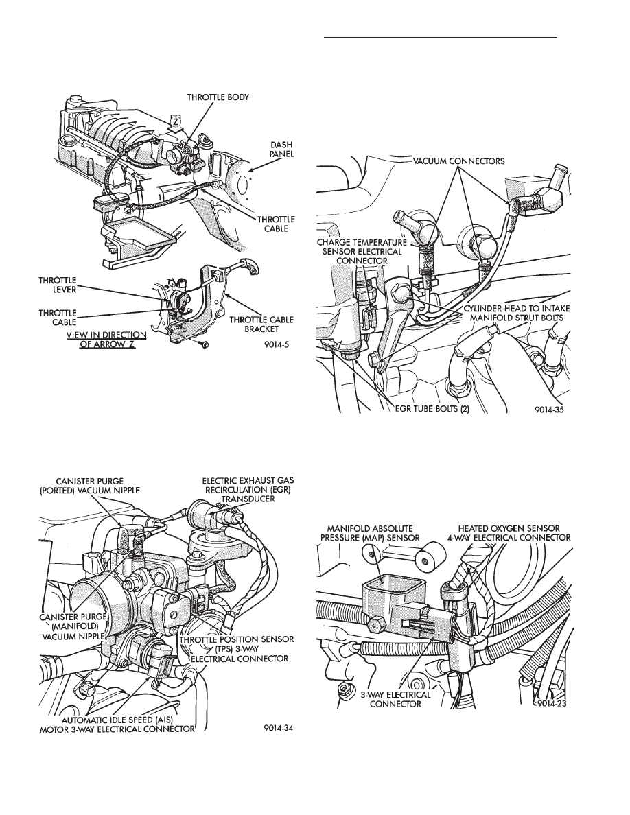
(4) Remove throttle cable (Fig. 3). Remove wiring
harness from throttle cable bracket.
(5) Remove automatic idle speed (AIS) motor and
throttle position sensor (TPS) wiring connectors from
throttle body (Fig. 4).
(e) Remove jumper wires.
(f) Continue fuel system service.
(6) Remove vacuum hose harness from throttle
body (Fig. 4).
(7) Remove PCV and brake booster hoses from air
intake plenum (Fig. 5).
(8) Remove EGR tube flange from intake plenum
(Fig. 5).
(9) Disconnect Charge Temperature Sensor electri-
cal connector. Remove vacuum harness connectors
from Intake Plenum (Fig. 5).
(10) Remove cylinder head to intake plenum strut
(Fig. 5).
(11) Disconnect MAP Sensor and heated Oxygen
Sensor electrical connection. Remove the engine
mounted ground strap (Fig. 6).
Fig. 3 Throttle Cable Attachment
Fig. 4 Electrical and Vacuum Connection to Throttle
Body
Fig. 5 Electrical and Vacuum Connections To Intake
Manifold
Fig. 6 MAP Sensor Electrical Connector
11 - 20
EXHAUST SYSTEM AND INTAKE MANIFOLD
Ä
Нет комментариевНе стесняйтесь поделиться с нами вашим ценным мнением.
Текст