Chrysler Le Baron, Dodge Dynasty, Plymouth Acclaim. Manual — part 276

(8) For
installation,
reverse
above
procedures.
Clean corrosion/dirt from the cable and wire termi-
nals before installing wiring to the solenoid.
BOSCH OR NIPPONDENSO STARTER—3.0L/
3.3L/3.8L ENGINE
(1) Disconnect NEGATIVE battery cable (Fig. 1).
(2) Raise vehicle.
(3) Remove three starter attaching bolts at engine/
transaxle (Fig. 4).
(4) Remove the two wire connector terminal nuts
and remove wiring connector (Bosch, Fig. 5) (Nippon-
denso, Fig. 6 or 7).
(5) Remove starter from vehicle (Bosch, Fig. 8)
(Nippondenso, Fig. 9).
(6) For
installation,
reverse
above
procedures.
Clean corrosion/dirt from the cable and wire termi-
nals before installing wiring to the solenoid.
STARTER COMPONENT REPLACEMENT
Caution: When servicing the starter assembly off
the vehicle, do not clamp the starter to a vice. In-
ternal damage may result.
Fig. 3 Bosch Starter—2.2L/2.5L Engine
Fig. 4 Remove or Install Attaching Bolts—Typical
Fig. 5 Wire Terminal Connections—Bosch Starter
Fig. 6 Wire Terminal Connections—3.0L
Engine—Nippondenso Starter
Fig. 7 Wire Terminal Connections—3.3L/3.8L
Engine—Nippondenso Starter
Ä
BATTERY/STARTER/GENERATOR SERVICE
8B - 5

NIPPONDENSO STARTER GEAR AND CLUTCH
REMOVAL AND INSTALLATION
(1) Remove the two gear housing attaching screws
and separate the gear housing from the solenoid
housing (Fig. 10). The pinion gear, pinion gear bear-
ing, and drive gear will be loose between the solenoid
housing and gear housing (Fig. 11). When reinstall-
ing pinion gear and bearing, wipe with a clean rag
and coat with lightweight high temperature wheel
bearing grease. Place the lubricated bearing and
gear over the bearing shaft in the gear housing (Fig.
12).
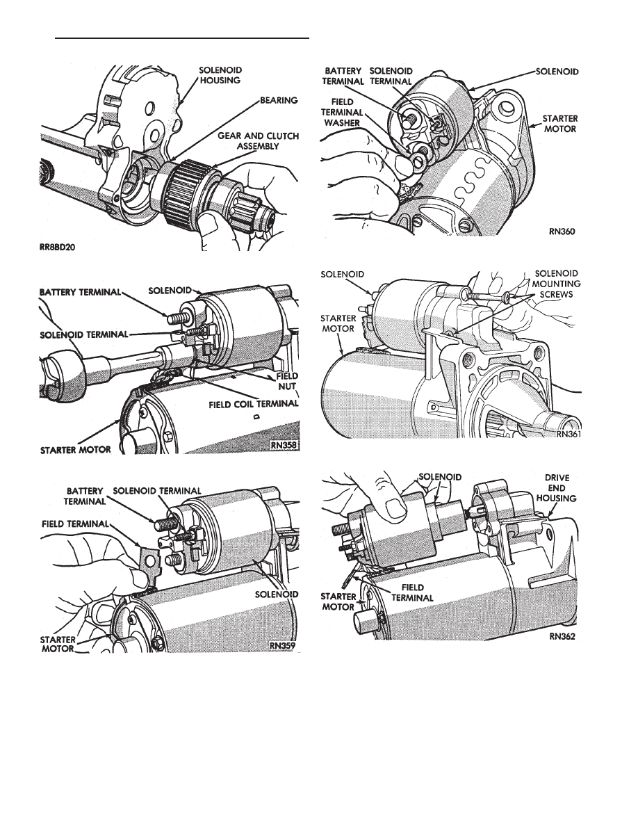
(2) Remove the starter gear and clutch assembly
from the solenoid housing (Fig. 13).
(3) For assemble, reverse above procedures.
BOSCH STARTER SOLENOID REPLACEMENT
(1) Remove field terminal nut (Fig. 14).
(2) Remove field terminal (Fig. 15).
(3) Remove field washer (Fig. 16).
(4) Remove three solenoid mounting screws (Fig.
17).
(5) Remove the solenoid from the starter assembly.
(6) For installation, reverse above procedures.
Fig. 8 Remove/Install Starter—Bosch—Typical
Fig. 9 Remove/Install
Starter—Nippondenso—Typical
Fig. 10 Remove or Install Gear Housing
Fig. 11 Remove or Install Drive and Pinion Gears
Fig. 12 Lubricate and Install Pinion Gear Bearing
8B - 6
BATTERY/STARTER/GENERATOR SERVICE
Ä
BOSCH STARTER GEAR AND CLUTCH
REPLACEMENT
(1) Remove solenoid assembly (Fig. 18).
(2) Remove the two through-bolts securing the
starter drive end housing to the motor housing (Fig.
19) and separate housings.
(3) Remove rubber seal (Fig. 20).
(4) Pull the gear and clutch assembly from the
drive end housing (Fig. 21).
(5) For installation, reverse above procedures.
STARTER INTERLOCK SWITCH: CLUTCH PEDAL
MOUNTED/MANUAL TRANSMISSION ONLY
For electrical diagnostics, refer to Group 8A, Bat-
tery/Starting/Charging Systems Diagnostics, Starter
relays.
Fig. 13 Gear and Clutch Assembly
Fig. 14 Field Terminal Nut
Fig. 15 Field Coil Terminal
Fig. 16 Field Terminal Washer
Fig. 17 Solenoid Mounting Screws
Fig. 18 Solenoid
Ä
BATTERY/STARTER/GENERATOR SERVICE
8B - 7

For replacement and adjustment of this switch, re-
fer to Group 6, Manual Transaxle Clutch, Manual
Transaxle Starter Interlock Switch.
NEUTRAL STARTER AND BACK-UP SWITCH
For
electrical
diagnostics
when
checking
the
starter circuits, refer to Group 8A, Battery/Starting/
Charging Systems Diagnostics, Starter Relays.
For removal and installation of neutral switch, re-
fer to Group 21, Transaxle Neutral Starter and
Back-up Switch Replacement.
Fig. 19 Through-Bolt
Fig. 20 Rubber Seal
Fig. 21 Starter Drive Gear Train
8B - 8
BATTERY/STARTER/GENERATOR SERVICE
Ä
Нет комментариевНе стесняйтесь поделиться с нами вашим ценным мнением.
Текст