Chrysler Le Baron, Dodge Dynasty, Plymouth Acclaim. Manual — part 52
3.0L MULTI-PORT FUEL INJECTION—GENERAL DIAGNOSIS
INDEX
page
page
Fuel System Diagram
. . . . . . . . . . . . . . . . . . . . 125
Visual Inspection
. . . . . . . . . . . . . . . . . . . . . . . . 125
FUEL SYSTEM DIAGRAM
The 3.0L MPI system is managed by the PCM. The
PCM receives inputs from various switches and sen-
sors (Fig. 1). Based on these inputs, the PCM adjusts
ignition timing and idle speed through various out-
put devices. Refer to the Multi-Port Fuel Injec-
tion—3.0L Engine section of this group for system
and component descriptions.
VISUAL INSPECTION
Perform a visual inspection for loose, disconnected,
or misrouted wires and hoses before diagnosing or
servicing the fuel injection system. A visual check
saves unnecessary test and diagnostic time. A thor-
ough visual inspection includes the following checks:
(1) Check for correct spark plug cable routing. En-
sure the cables are completely connected to the spark
plugs and distributor.
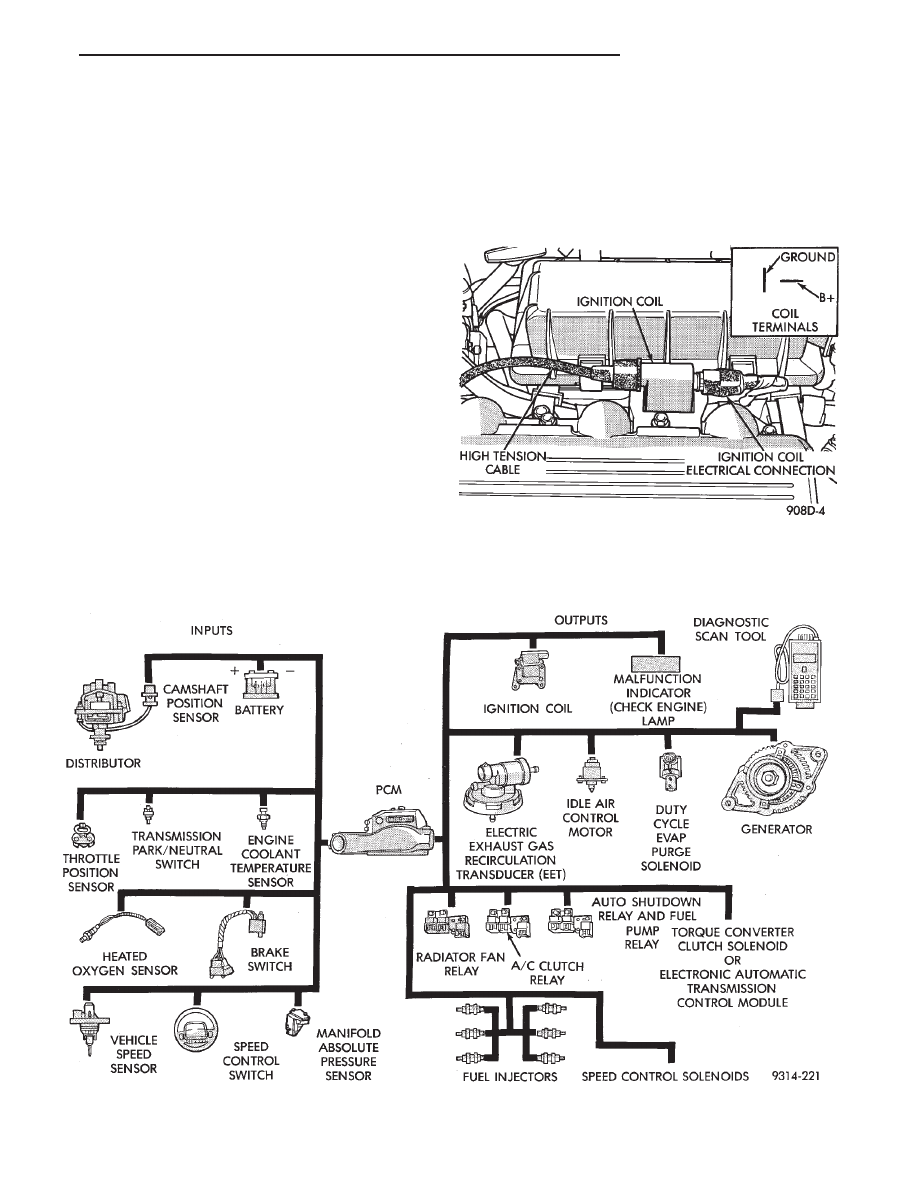
(2) Check ignition coil electrical connections (Fig.
2).
(3) Verify the electrical connector is attached to
the Purge Solenoid (Fig. 3).
Fig. 1 Multi-Port Fuel Injection Components
Fig. 2 Ignition Coil Electrical Connection
Ä
FUEL SYSTEMS
14 - 125
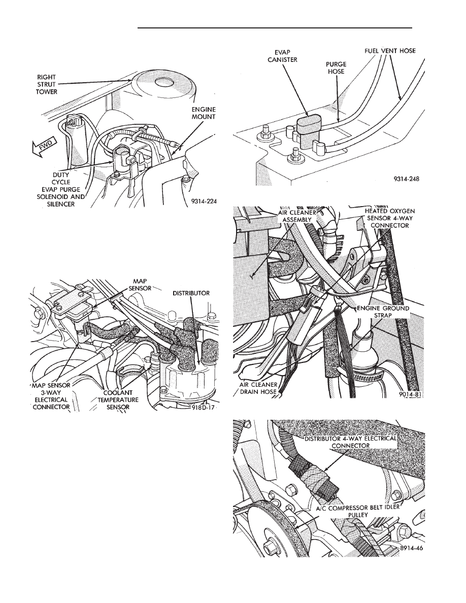
(4) Verify vacuum connection at Purge Solenoid is
secure and not leaking (Fig. 3).
(5) Verify the electrical connector is attached to
the MAP sensor (Fig. 4).
(6) Check MAP sensor hose at MAP Sensor Assem-
bly (Fig. 4), and at Vacuum Connection at Intake
Plenum Fitting.
(7) Check generator wiring connections. Ensure
the accessory drive belt has proper tension.
(8) Verify hoses are securely attached to the vapor
canister (Fig. 5).
(9) Verify the engine ground strap is attached at
the engine and dash panel (Fig. 6).
(10) Ensure the heated oxygen sensor connector is
connected to the harness connector (Fig. 6).
(11) Verify the distributor connector is connected
to the harness connector (Fig. 7).
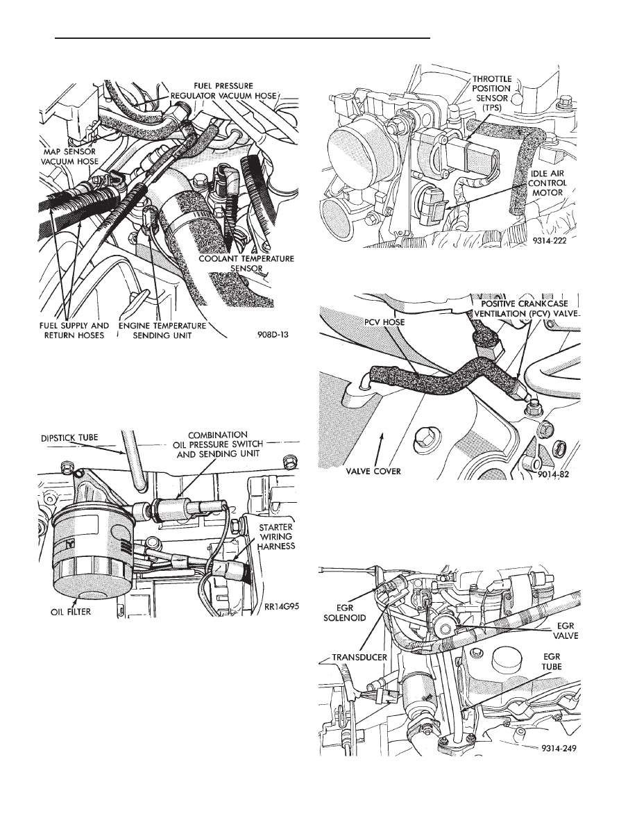
(12) Verify the coolant temperature sensor connec-
tor is connected to the harness connector (Fig. 8).
(13) Check vacuum hose connection at fuel pres-
sure regulator and intake plenum connector (Fig. 8).
Fig. 3 Duty Cycle EVAP Canister Purge Solenoid
Fig. 4 Map Sensor Electrical and Vacuum
Connections
Fig. 5 Vapor Canister
Fig. 6 Oxygen Sensor Connector
Fig. 7 Distributor Connector
14 - 126
FUEL SYSTEMS
Ä
(14) Ensure the harness connector is securely at-
tached to each fuel injector.
(15) Check the oil pressure sending unit electrical
connection (Fig. 9).
(16) Check hose connections at throttle body (Fig.
10).
(17) Check throttle body electrical connections
(Fig. 10).
(18) Check PCV hose connections (Fig. 11).
(19) If equipped, check EGR system vacuum hose
connections (Fig. 12).
(20) If equipped, check EGR tube to intake plenum
connections (Fig. 12).
(21) Inspect the electronic EGR transducer sole-
noid electrical connector.
(22) Ensure the vacuum connections at the elec-
tronic EGR transducer is secure and not leaking.
Fig. 8 Coolant Temperature Sensor and Vacuum
Connections
Fig. 9 Oil Pressure Sending Unit Electrical
Connection
Fig. 10 Throttle Body Electrical and Vacuum Hose
Connections
Fig. 11 Positive Crankcase Ventilation (PCV) System
Fig. 12 EGR System Vacuum Hose Connections
Ä
FUEL SYSTEMS
14 - 127
(23) Check Power Brake Booster and Speed Con-
nections (Figs. 13 and 14).
(24) Inspect engine harness to main harness con-
nections.
(25) Check all automatic transaxle electrical con-
nections (Fig. 15).
(26) Check the vehicle speed sensor electrical con-
nection (Fig. 16).
(27) Inspect the PCM 60-way electrical connector
for damage or spread terminals. Verify the 60-way
connector is fully inserted into the socket of the
PCM. Ensure wires are not stretched or pulled out of
the connector (Figs. 17, 18, and 19).
Fig. 13 Power Brake Booster and Speed Control
Vacuum Hose Connections (Without Anti-lock
Brakes)
Fig. 14 Speed Control Vacuum Hose Connection
(With Anti-lock Brakes)
Fig. 15 Automatic Transaxle Electrical Connections
Fig. 16 Vehicle Speed Sensor Electrical Connector
Fig. 17 PCM—AA Body
14 - 128
FUEL SYSTEMS
Ä
Нет комментариевНе стесняйтесь поделиться с нами вашим ценным мнением.
Текст