Chrysler Le Baron, Dodge Dynasty, Plymouth Acclaim. Manual — part 69

(12) Transfer Required parts to the new power
steering pump assembly before installing in vehicle.
INSTALL
(1) Install the power steering pump assembly back
in vehicle in reverse order of removal.
(2) Hold power steering pump against mounting
plate. Align power steering pump mounting holes
with mounting holes in plate and install bolts (Fig.
9). Torque the 2 power steering pump to mounting
plate bolts to 54 N
Im (40 ft. lbs.).
(3) Install the rear power steering pump to engine
block support bracket, onto the stud on back of power
steering pump (Fig. 8). Then install the 2 bolts
mounting the support bracket to the engine block.
Torque the 2 support bracket to engine block mount-
ing bolts to 54 N
Im (40 ft. lbs.).
(4) Install the nut on stud of power steering pump
attaching pump to rear support bracket (Fig. 8).
Torque nut to 54 N
Im (40 ft. lbs.)
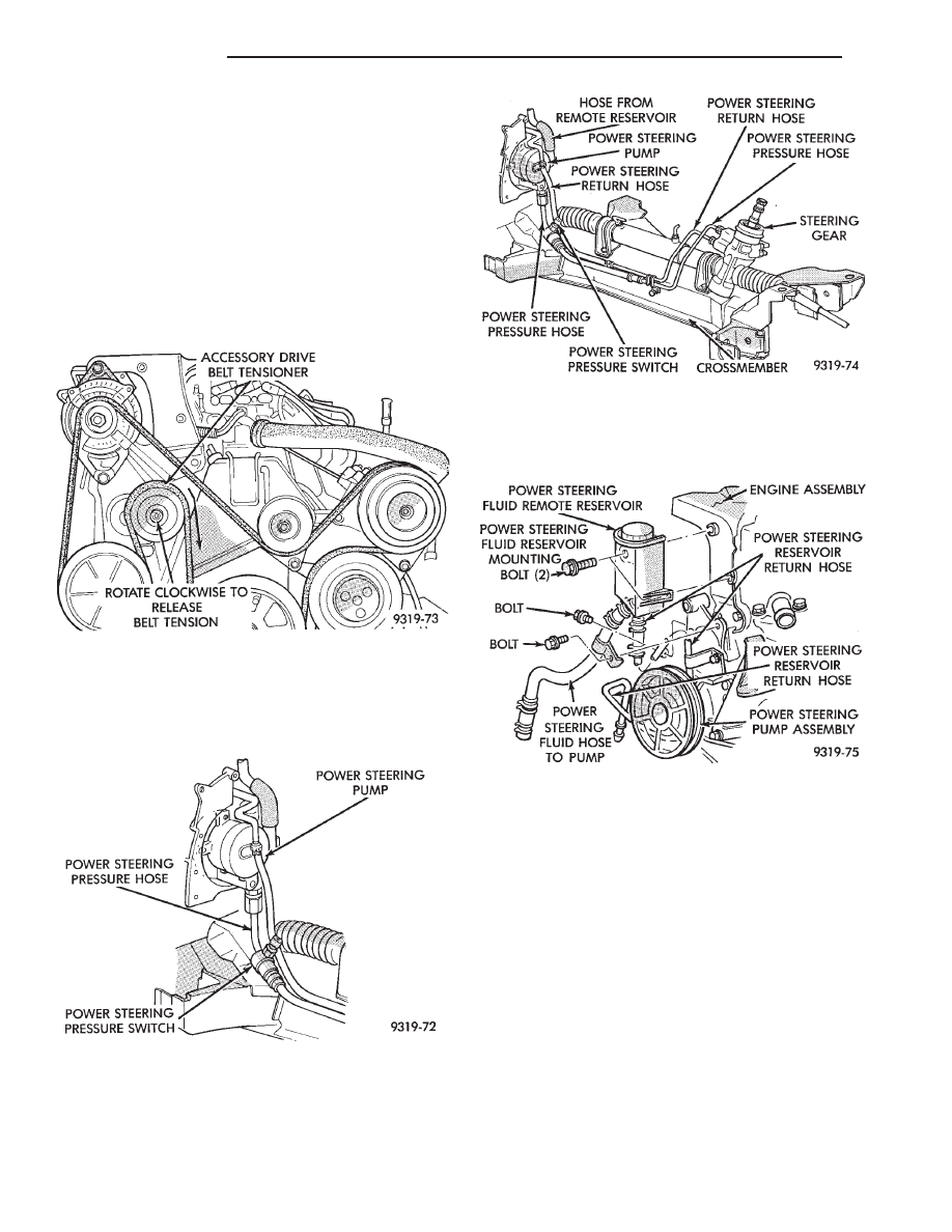
(5) Install the high pressure power steering fluid
line on the power steering pump outlet fitting (Fig.
7). Torque the high pressure fluid line to power
steering pump fitting to 31 N
Im (275 in. lbs.).
(6) Install the low pressure power steering fluid
hose onto the power steering gear fluid tube (Fig. 7).
Install hose clamp on hose. Be sure hose clamp is
installed beyond upset bead on tube.
(7) Install the exhaust pipe back on the exhaust
manifold. Install the nut, bolt and spring assemblies
and torque bolts to 28 N
Im (250 in. lbs.).
(8) Install vehicle’s wiring harness connector (if
applicable to vehicle being serviced) onto the power
steering pressure switch (Fig. 6).
(9) Lower vehicle.
(10) Install the power steering pump filler tube
and dip stick assembly on the neck of the power
steering pump (Fig. 5). Install the bolt (Fig. 5) at-
taching the filler tube/dip stick assembly to the gen-
erator bracket, then torque bolt to 11 N
Im (100 in.
lbs.).
(11) Position the hose clamp on the filler tube as-
sembly rubber boot and adequately tighten hose
clamp.
(12) Install the serpentine accessory drive belt on
engine (Fig. 4). See Cooling, Group 7 for detailed in-
stallation procedure.
CAUTION: Do not use automatic transmission fluid
in power steering system. Only use Mopar
T
, Power
Steering Fluid, or equivalent.
(13) Fill power steering pump reservoir to correct
fluid level.
(14) Connect the negative battery cable back on
the negative battery post.
Fig. 7 Power Steering Hose Remove/Replace
Fig. 8 Power Steering Support Bracket
Fig. 9 Power Steering Pump Mounting 3.0L
Ä
STEERING
19 - 15
(15) Start engine and turn steering wheel several
times from stop to stop to bleed air from fluid in sys-
tem. Stop engine, check fluid level, and inspect sys-
tem for leaks. See Checking Fluid Level.
3.3 & 3.8 LITER
REMOVE
(1) Remove the (-) negative battery cable from the
battery and isolate cable.
(2) Remove the serpentine accessory drive belt
from engine (Fig. 10). See Cooling, Group 7 for de-
tailed removal procedure.
(3) Raise vehicle See Hoisting, Group 0.
(4) Remove vehicle’s wiring harness connector (if
applicable to vehicle being serviced) from the power
steering pressure switch (Fig. 11).
(5) Put oil drain pan under vehicle to catch power
steering fluid. Remove hose clamp and low pressure
fluid hose from power steering pump (Fig. 12).
(6) Remove hose clamp and hose to the power steer-
ing pump, from the remote fluid reservoir (Fig. 13).
Drain off excess power steering fluid from hoses.
(7) Remove the power steering, fluid pressure line
(Fig. 12) from the power steering pump. Drain excess
power steering fluid from tube.
(8) Remove right front wheel and tire from vehicle.
This will aid in access to the power steering pump
mounting bolts.
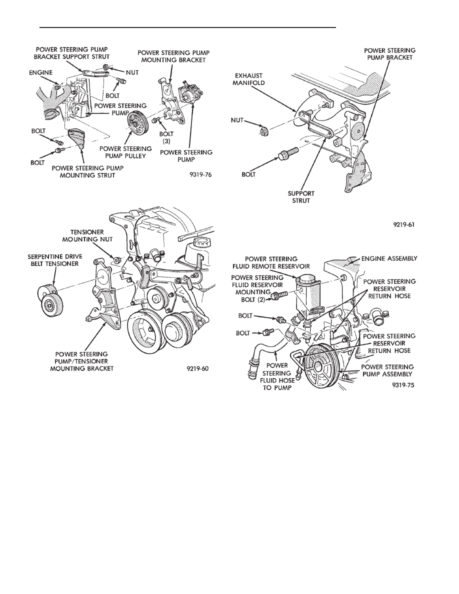
(9) Remove the 3 bolts holding the power steering
pump to the generator, power steering and belt ten-
sioner mounting bracket (Fig. 14).
(10) Remove nut and bolt holding the engine block,
to power steering pump support strut. Remove strut
from engine and power steering pump (Fig. 14) Lay
the power steering pump assembly down on top
of the steering gear. It will be removed later from
the top.
(11) Remove nut which holds serpentine drive belt
tensioner to its mounting bracket (Fig. 15). Remove
tensioner assembly from bracket.
Fig. 10 Serpentine Drive Belt Routing
Fig. 11 Power Steering Pressure Switch Location
3.3 & 3.8L
Fig. 12 Power Steering Hose Routing 3.3 & 3.8L
Fig. 13 Power Steering Remote Fluid Reservoir And
Tube
19 - 16
STEERING
Ä
(12) Remove nut and bolt attaching the generator/
power steering pump bracket, support strut (Fig. 16).
(13) Lower vehicle.
(14) Remove the 2 bolts holding the power steering
fluid reservoir to the generator bracket. Remove the
bolt attaching the tube/hose assemblies to the power
steering pump bracket (Fig. 17). Then remove the
fluid reservoir and tube/hose as an assembly from ve-
hicle.
(15) Remove the engine wiring harness routing
clip from the generator bracket.
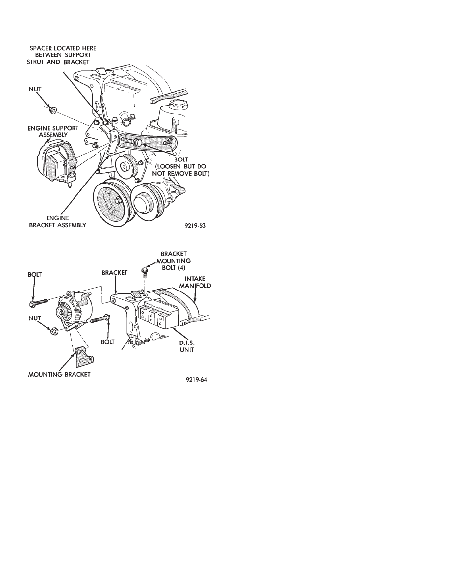
(16) Loosen but DO NOT REMOVE the bolt (Fig.
18) holding the engine bracket assembly to the en-
gine support assembly.
(17) Remove upper generator to generator bracket
mounting bolt (Fig. 19). Rotate the generator assem-
bly back toward the dash panel.
(18) Remove the 4 bolts holding the generator
bracket to the engine and intake manifold (Fig. 19).
Remove generator bracket from engine.
(17) Remove the generator assembly, to lower gen-
erator bracket bolt (Fig. 19). Without removing wir-
ing harness from generator. Remove generator from
bracket and lay generator on top of intake manifold.
(18) Remove the power steering pump out through
the top, in the area between engine and dash panel
where the generator was mounted.
(19) Transfer the required parts from the removed
power steering pump, to the replacement power
steering pump.
Fig. 14 Power Steering Pump Mounting 3.3 & 3.8 ltr.
Fig. 15 Serpentine Belt Tensioner
Fig. 16 Bracket Support Strut
Fig. 17 Power Steering Fluid Reservoir Mounting
Ä
STEERING
19 - 17
INSTALL
(1) Install power steering pump back in vehicle,
laying it on the steering gear. Do not mount it to the
power steering pump bracket.
(2) Install generator back on the lower generator
bracket and install bolt and nut (Fig. 19). Do not
tighten bolt at this time.
(3) Install the generator bracket back on engine and
intake manifold. Loosely install the 4 generator
bracket to engine attaching bolts (Fig. 19). Be sure
the SPACER (Fig. 18) is installed between the
engine
mounting
strut
and
the
generator
bracket.
(4) Temporarily install the serpentine belt tensioner
bolt through both generator brackets. This will align
all generator bracket mounting holes (Fig. 15). Then
torque
the
4
generator
bracket
to
engine
and intake manifold mounting bolts to 54 N
Im (40 ft.
lbs.). Then remove the serpentine belt tensioner from
bracket. It will be installed on the bracket in a
later step.
(5) Tighten the bolt holding the engine bracket as-
sembly to the engine support assembly (Fig. 18) to 150
N
Im (110 ft. lbs.).
(6) Attach the engine wiring harness routing clip to
the generator bracket.
(7) Install the generator to generator bracket attach-
ing bolt (Fig. 19). Torque bolt to 54 N
Im (40 ft. lbs.).
Tighten the lower generator pivot bolt to 54 N
Im (40 ft.
lbs.).
(8) Install the power steering pump fluid reservoir
and tube/hose assembly onto the power steering pump
bracket and generator bracket (Fig. 17). Torque the 2
bolts holding the reservoir to the generator bracket to
5 N
Im (45 in. lbs.). Torque the 1 bolt holding the
tube/hose assembly to the power steering pump
bracket to 12 N
Im (105 in. lbs.).
(9) Raise vehicle See Hoisting, Group 0.
(10) Install
the
strut
assembly
power
steering/generator bracket to engine (Fig. 16). Torque
the nut and bolt holding the strut assembly to bracket
and the exhaust manifold stud to 54 N
Im (40 ft. lbs).
(11) Install the serpentine drive belt tensioner onto
the power steering/generator bracket (Fig. 15). Install
the tensioner to bracket retaining nut and torque to 54
N
Im (40 ft. lbs.).
(12) Install the power steering pump on bracket, by
aligning the 3 mounting holes in pump with mounting
holes in bracket (Fig. 14). Install the 3 power steering
pump to bracket mounting bolts. Torque power steer-
ing pump mounting bolts to 54 N
Im (40 ft. lbs.).
(13) Install the support strut, engine block to power
steering pump on pump stud (Fig. 14). Install the nut
and bolt holding the strut to the power steering pump
and engine block and torque to 54 N
Im (40 ft. lbs.).
(14) Install the power steering fluid pressure line
onto the output fitting of the power steering pump (Fig.
12). Torque the pressure line pump fitting nut to 31
N
Im (275 in. lbs.). Before connecting the pressure
line to power steering pump inspect the O-ring
on the pressure line for damage.
(15) Install vehicle’s wiring harness connector (if
applicable to vehicle being serviced) onto the power
steering pressure switch (Fig. 11).
(16) Install the power steering fluid, low pressure
return hose on the power steering pump low pressure
fitting (Fig. 12). Then install the hose from the remote
reservoir onto the power steering pump (Fig. 13). Be
sure all hose clamps are properly reinstalled.
(17) Install right front tire and wheel on vehicle.
Install the wheel stud nuts and torque to 129 N
Im (95
ft. lbs.).
Fig. 18 Engine Bracket Support Assembly
Fig. 19 Generator Mounting
19 - 18
STEERING
Ä
Нет комментариевНе стесняйтесь поделиться с нами вашим ценным мнением.
Текст