Chrysler Le Baron, Dodge Dynasty, Plymouth Acclaim. Manual — part 131
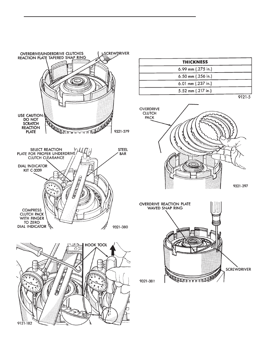
Snap ring ends must be located within one
finger of the input clutch hub. Be sure that snap
ring is fully seated, by pushing with screwdriver,
into snap ring groove all the way around.
Underdrive clutch pack clearance must be 0.91
to 1.47 mm (.036 to .058 inch). Select the proper
reaction plate to achieve specifications:
Fig. 17 Seating Tapered Snap Ring
Fig. 18 Set Up Dial Indicator for Clutch Clearance
Fig. 19 Use Hook Tool to Raise One Clutch Disc
UNDERDRIVE REACTION PLATE CHART
Fig. 20 Install OD Clutch Pack
Fig. 21 Install Waved Snap Ring
Ä
TRANSAXLE
21 - 129
The overdrive (OD) clutch pack clearance is
1.07 to 2.44 mm (.042 to .096 inch). If not within
specifications, the clutch is not assembled properly.
There is no adjustment for the OD clutch clearance.
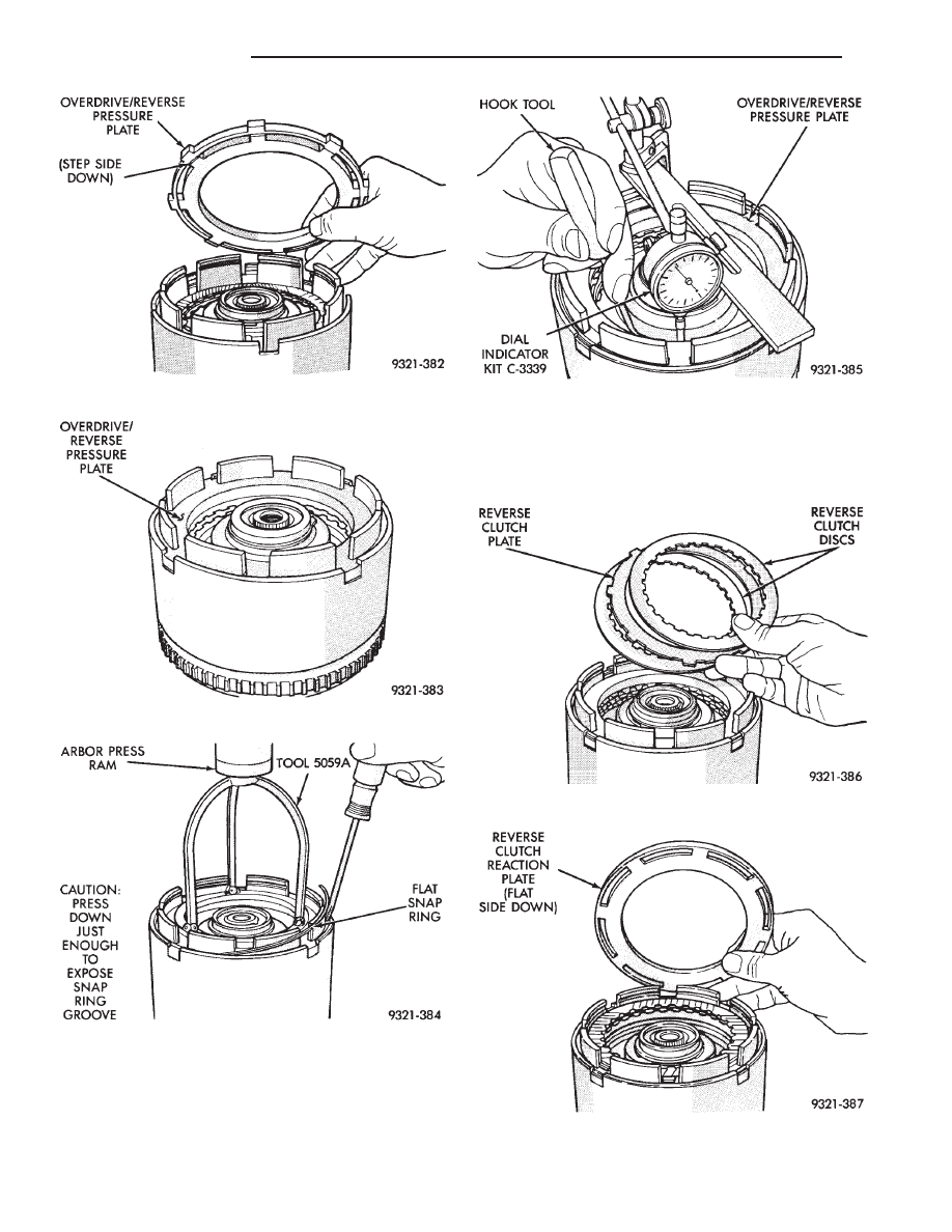
Fig. 22 OD/Reverse Pressure Plate
Fig. 23 Pressure Plate Installed
Fig. 24 Install Flat Snap Ring
Fig. 25 Check OD Clutch Pack Clearance
Fig. 26 Install Reverse Clutch Pack
Fig. 27 Install Reaction Plate
21 - 130
TRANSAXLE
Ä

The reverse clutch pack clearance is 0.76 to
1.24 mm (.030 to .049 inch). Select the proper reverse
clutch snap ring to achieve specifications:
All clutch clearances in the input clutch retainer
have now been checked and approved.
To complete the assembly of the input clutch re-
tainer, the reverse clutch and the overdrive clutch
must be removed from the retainer.
CAUTION: Do not intermix clutch parts. Keep in ex-
act same order.
Now proceed with the next phase of the assembly:
REVERSE CLUTCH SNAP RING CHART
Fig. 31 Install No. 2 Needle Bearing
Fig. 32 Install Underdrive Shaft Assembly
Fig. 28 Install Reverse Clutch Snap Ring
Fig. 29 Seating Snap Ring to Determine Reverse
Clutch Clearance
Fig. 30 Check Reverse Clutch Pack Clearance
Ä
TRANSAXLE
21 - 131
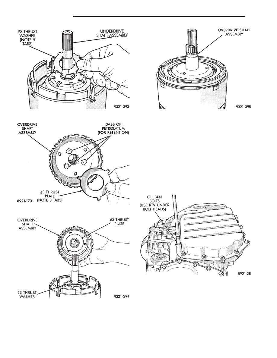
Now that both shaft assemblies and thrust washers
are properly installed, reinstall overdrive clutch and
reverse clutch as shown in Figures 20 through 28.
Rechecking these clutch clearances is not neces-
sary, as they were set and approved previously.
VALVE BODY-RECONDITION
Prior to removing any transaxle subassemblies, plug
all openings and thoroughly clean exterior of the unit,
preferably by steam. Cleanliness through entire disas-
sembly and assembly cannot be overemphasized. When
disassembling, each part should be washed in a suit-
able solvent, then dried by compressed air. Do not
wipe parts with shop towels. All mating surfaces in
the transaxles are accurately machined; therefore,
careful handling of all parts must be exercised to avoid
nicks or burrs.
Tag all springs, as they are removed, for reas-
sembly identification.
Fig. 33 Install No. 3 Thrust Washer
Fig. 34 Install No. 3 Thrust Plate
Fig. 35 Install Overdrive Shaft Assembly
Fig. 36 Input Clutch Assembly
Fig. 1 Oil Pan Bolts
21 - 132
TRANSAXLE
Ä
Нет комментариевНе стесняйтесь поделиться с нами вашим ценным мнением.
Текст