Chrysler Le Baron, Dodge Dynasty, Plymouth Acclaim. Manual — part 87

Rubber boots must be serviced with the strap and
buckle clamp. Use the Clamp Installer, Special Tool
C-4653. Proceed with the boot installation as follows:
(1) Slide the small end of the boot over the shaft.
Position the boot to the edge of the locating mark or
groove, whichever is appropriate (Fig. 1).
(2) Install the C/V joint. See Inner or Outer C/V
Joint Assemble.
(3) Slide the large diameter of the boot into the lo-
cating groove (Fig. 6).
(4) Wrap binding strap around boot twice, PLUS
63 mm (2-1/2 inches) (Fig. 2).
(5) Pass the strap through the buckle and fold it
back about 29 mm (1-1/8 inches) on the inside of the
buckle (Fig. 3).
(6) Put the strap around the boot with the eye of
the buckle toward you (Fig. 4). Wrap the strip
around the boot once and pass it through the buckle,
then wrap it around a second time also passing it
through the buckle.
(7) Fold the strip back slightly to prevent it from
slipping backwards (Fig. 5).
(8) Open the tool all the way and place strip in
narrow slot approximately 13 mm (1/2 inch) from
buckle (Fig. 6).
Fig. 2 Measure & Cut Binding Strap
Fig. 3 Install Buckle on Strap
Fig. 4 Wrap Strap (through Buckle Eye) Twice
Fig. 5 Fold Strap Lightly to Keep Position
Fig. 6 Open Tool, Position Strap in Narrow Slot 1/2
Inch from Buckle
Ä
SUSPENSION AND DRIVESHAFTS
2 - 45
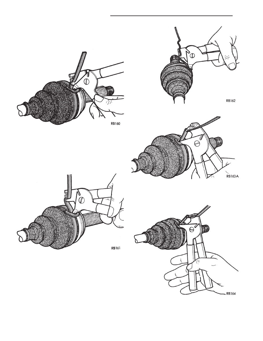
(9) Hold the binding strip with the left hand and
push the Tool forward and slightly upward. Then fit
the hook of the Tool into the eye of the buckle (Fig.
7).
(10) Tighten the strip by closing the tool handles
(Fig. 8). Then rotate the tool (handles) downward
while slowly releasing the pressure on the tool han-
dles. Allow the tool (handles) to open progressively.
Then open the tool entirely and remove them side-
ways.
(11) If the strap is not tight enough, engage the
tool a second or even a third time, always about 13
mm (1/2 inch) from the buckle (Fig. 9). When tight-
ening always be careful to see that the strap slides in
a straight line and without resistance in the buckle,
that is without making a fold. An effective grip will
be obtained only by following the above instructions.
(12) Fig. 10 shows WHAT NOT TO DO, NEVER
fold the strap back or bring the tool down while
tightening, this action will break the strap.
(13) Fig. 11 shows how to pull the tool down while
releasing the pressure on the tool handle.
Fig. 7 Push Tool Forward & Fit into Buckle Eye
Fig. 8 Tighten Strap
Fig. 9 Tighten Strap (if Required)
Fig. 10 What Not to Do
Fig. 11 Correct Tightening Procedure
2 - 46
SUSPENSION AND DRIVESHAFTS
Ä
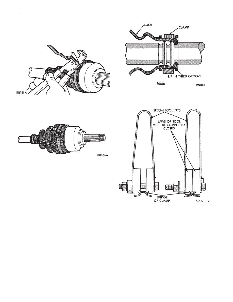
(14) If the strip is tight enough. Remove the tool
sideways and cut off the strap 3 mm (1/8 inch), so
that it does not overlap the edge of the buckle. Com-
plete job by folding the strip back neatly (Fig. 12).
(15) Fig. 13 shows the finished binding strap type
clamp in position, correctly fitted and unable to come
loose.
(16) After attaching the C/V joint boot to the shaft.
Install the inner or outer C/V joint following proce-
dures under Inner C/V Joint Assemble or Outer C/V
Joint Assemble.
(17) Slip the large end of the boot on the housing
and align it in the boot groove.
(18) Repeat steps 2 - 13 for boot clamping.
S.S.G. C/V joints use two different type boots, one
is made of plastic and the other of rubber. The plas-
tic boot requires a heavy duty clamp and Installer,
Special Tool C-4975. The soft boot requires a clamp
with round edges that prevents the clamp from cut-
ting the boot. Proceed with boot installation as fol-
lows.
The hard plastic boots used on the G.K.N. C/V
Joints. Also use this procedure for installation of the
boot clamp to C/V Joint.
LEFT INNER, LEFT AND RIGHT OUTER C/V
JOINT WITH PLASTIC BOOTS
(1) Slide small clamp onto shaft.
(2) Position small end of boot over interconnecting
shaft with lip of boot in third groove, towards center
of interconnecting shaft (Fig. 14).
(3) Position clamp evenly over boot. Place clamp
installer Tool C-4975 over bridge of clamp and
tighten the nut until the jaws of the tool are closed
completely, face to face (Fig. 15).
(4) After attaching the boot to the shaft. Install
the C/V joint following the procedure outlined under
Inner C/V Joint Assemble or Outer C/V Joint As-
semble.
(5) Position the large end of boot on housing and
install clamp, crimp bridge of clamp with Crimper,
Special Tool C-4975.
CAUTION: Use only the clamps provided in the boot
package for this application, otherwise damage to
the boot or C/V joint may occur.
RIGHT INNER C/V JOINT WITH RUBBER BOOT
(1) Slide small end boot clamp onto interconnect-
ing shaft.
Fig. 12 Cut Strap 1/8 Inch from Buckle
Fig. 13 Correctly Installed Clamp
Fig. 14 Boot and Clamp Positioning S.S.G.
Fig. 15 Closing Clamp Bridge
Ä
SUSPENSION AND DRIVESHAFTS
2 - 47
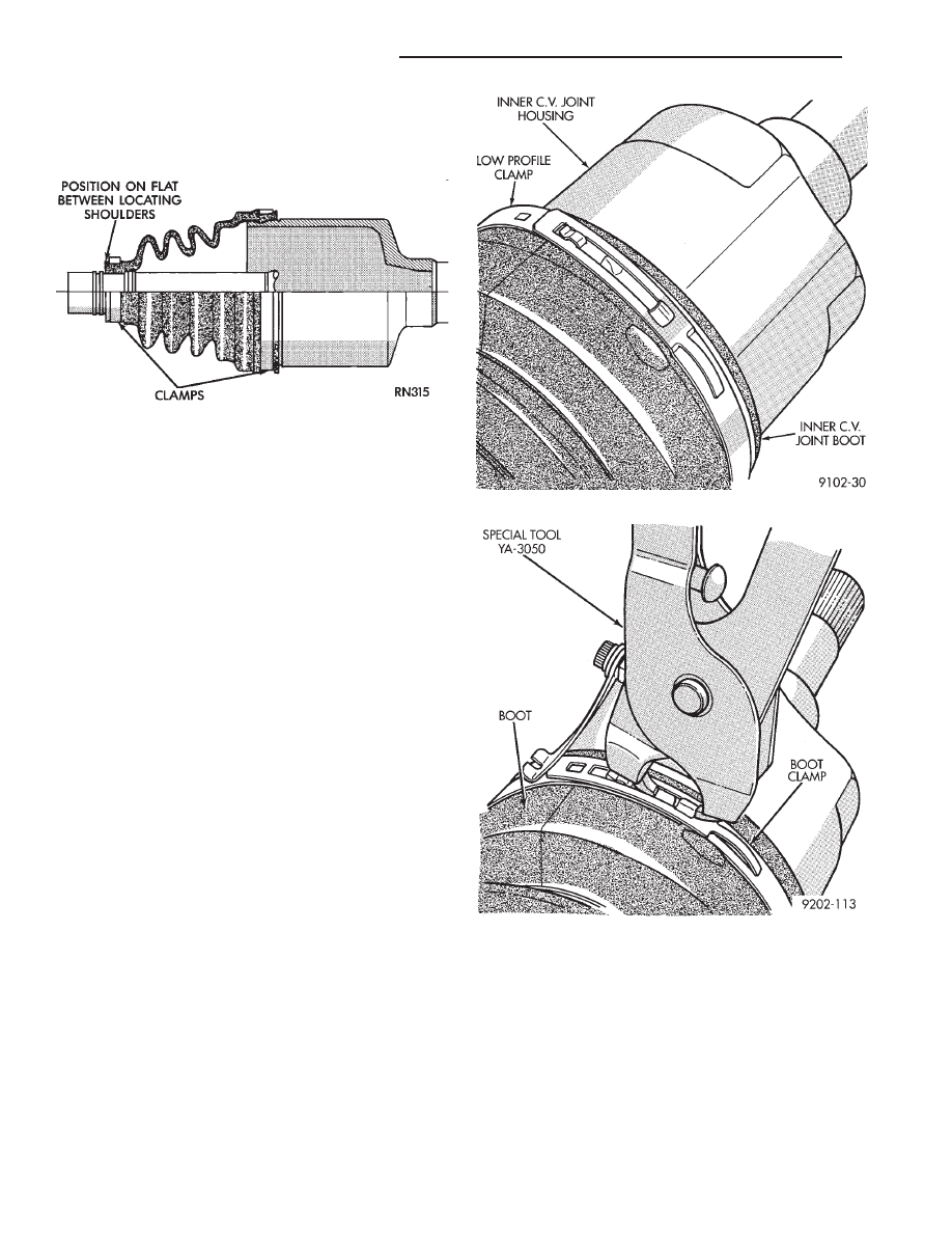
(2) Install boot onto interconnecting shaft, position
boot on the flat between the locating shoulders (Fig. 16).
(3) Position clamp on boot and crimp bridge of
clamp with Crimper Special Tool C-4124.
(4) Install the C/V Joint following the procedure
outlined under Inner C/V Joint Assemble.
(5) Position the large end of boot on housing and
install clamp, crimp bridge of clamp with Crimper,
Special Tool C-4124.
CAUTION: During any service procedures where
knuckle and driveshaft are separated, thoroughly
clean seal and wear sleeve with suitable solvent
and lubricate BOTH components at assembly. Do
not allow solvent to contact boot.
Lubricate wear sleeve (and seal) with Mopar Multi-
Purpose Lubricant, or equivalent, as follows:
Wear Sleeve: Apply a full circumference 6 mm
(1/4 inch) bead of lubricant to seal contact area. See
(Fig. 11), Driveshaft Assemblies Install.
Seal: Fill lip to housing cavity (full circumference)
and wet seal lip with lubricant.
S.S.G INNER C/V JOINT LARGE CLAMP
(MANUAL TRANS ONLY)
(1) Install small clamp and inner C/V joint housing
according to the procedures outlined in this manual.
(2) Position the boot over the outer C/V joint.
(3) Slide the large band clamp over the boot and
position it evenly in the groove on the inner C/V
joint boot. (Fig. 17).
(4) Use Clamp Locking Tool Snap-On YA3050 or
equivalent shown in (Fig. 18) to install the clamp on
the boot.
(5) Place the prongs of the clamp locking tool in
the holes on the clamp and squeeze together until
the two ends meet (Fig. 18).
DAMPER WEIGHTS
Damper weights are used on the left driveshaft as-
semblies of all front wheel drive vehicles (Fig. 19).
These weights are attached to the interconnecting
shaft and are available as a separate service part.
They should be removed from the driveshaft assem-
bly during driveshaft positioning specification proce-
dures. When the weights are attached between the
locating shoulders, tighten the fasteners to the fol-
lowing specifications:
• S.S.G. — 28 NIm (21 ft. lbs.)
• G.K.N. — 30 NIm (23 ft. lbs.)
DRIVESHAFT POSITIONING SPECIFICATIONS
Front wheel drive vehicles have engine mounts with
slotted holes allowing for side to side positioning of the
engine. If the vertical bolts on right or left upper engine
Fig. 16 Right Inner C/V Joint S.S.G.
Fig. 17 Boot Clamp Installed
Fig. 18 Locking Boot Clamp
2 - 48
SUSPENSION AND DRIVESHAFTS
Ä
Нет комментариевНе стесняйтесь поделиться с нами вашим ценным мнением.
Текст