Chrysler Le Baron, Dodge Dynasty, Plymouth Acclaim. Manual — part 63
3.3L AND 3.8L MULTI-PORT FUEL INJECTION—SERVICE PROCEDURES
INDEX
page
page
Camshaft Position Sensor Service
. . . . . . . . . . . 176
Crankshaft Position Sensor
. . . . . . . . . . . . . . . . 176
EVAP Canister Purge Solenoid Service
. . . . . . . 175
Fuel Injector
. . . . . . . . . . . . . . . . . . . . . . . . . . . 174
Fuel Injector Rail Assembly
. . . . . . . . . . . . . . . . 170
Fuel Pressure Regulator
. . . . . . . . . . . . . . . . . . 173
Fuel System Pressure Release Procedure
. . . . . 169
Heated Oxygen Sensor (O
2
Sensor) Service
. . . 177
Idle Air Control Motor
. . . . . . . . . . . . . . . . . . . . 170
Manifold Absolute Pressure (MAP) Sensor
. . . . . 175
PCM Service
. . . . . . . . . . . . . . . . . . . . . . . . . . . 175
Throttle Body
. . . . . . . . . . . . . . . . . . . . . . . . . . . 169
Throttle Body Removal
. . . . . . . . . . . . . . . . . . . 169
Throttle Position Sensor
. . . . . . . . . . . . . . . . . . 169
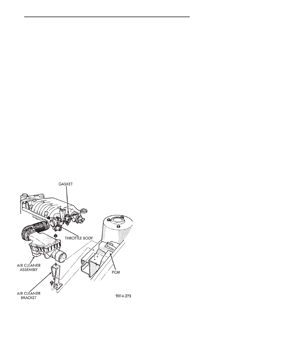
THROTTLE BODY REMOVAL
(1) Disconnect negative battery cable.
(2) Remove the air cleaner to throttle body hose
clamp. Remove the nut holding the air cleaner as-
sembly to the air cleaner bracket. Remove the air
cleaner (Fig. 1).
(3) Remove throttle and the speed control cables.
(4) Disconnect electrical connectors from the idle
air control motor and throttle position sensor (TPS).
(5) Disconnect vacuum hoses from throttle body.
(6) Remove throttle body to intake manifold at-
taching nuts.
(7) Remove throttle body and gasket.
(8) Reverse the above procedure for installation.
THROTTLE BODY
When servicing throttle body components, always
reassemble components with new O-rings and seals
where applicable (Fig. 2). Never use lubricants on
O-rings or seals, damage may result. If assembly of
component is difficult, use water to aid assembly.
Use care when removing hoses to prevent damage to
hose or hose nipple.
FUEL SYSTEM PRESSURE RELEASE PROCEDURE
WARNING: THE 3.3L AND 3.8L MPI FUEL SYSTEMS
ARE UNDER A CONSTANT PRESSURE OF AP-
PROXIMATELY 330 KPA (48 PSI). RELEASE FUEL
SYSTEM
PRESSURE
BEFORE
SERVICING
THE
FUEL PUMP, FUEL LINES, FUEL FILTER, THROT-
TLE BODY OR FUEL INJECTORS.
(1) Disconnect negative cable from battery.
(2) Remove fuel filler cap.
(3) Remove the protective cap from the fuel pres-
sure test port on the fuel rail (Fig. 3).
(4) Place the open end of fuel pressure release
hose, tool number C-4799-1, into an approved gaso-
line container. Connect the other end of hose
C-4799-1 to the fuel pressure test port. Fuel pressure
will bleed off through the hose into the gasoline con-
tainer. Fuel gauge C-4799-A contains hose C-4799-1.
(5) Continue fuel system service.
THROTTLE POSITION SENSOR
REMOVAL
(1) Disconnect negative cable from battery.
(2) Remove electrical connector from throttle posi-
tion sensor.
(3) Remove
throttle
position
sensor
mounting
screws (Fig. 4).
(4) Lift throttle position sensor off throttle shaft.
INSTALLATION
(1) Install throttle position sensor on throttle shaft.
Install mounting screws. Tighten screw to 2 N
Im (17
in. lbs.) torque.
(2) Connect electrical connector to throttle position
sensor.
(3) Connect negative cable to battery.
Fig. 1 Throttle Body Assembly
Ä
FUEL SYSTEMS
14 - 169

IDLE AIR CONTROL MOTOR
REMOVAL
(1) Disconnect negative cable from battery.
(2) Remove electrical connector from idle air con-
trol motor.
(3) Remove idle air control motor mounting screws
(Fig. 5).
(4) Remove idle air control motor from throttle
body. Ensure the O-ring is removed with the motor.
INSTALLATION
(1) New idle air control motors have a new O-ring
installed on it. If pintle measures more than 1 inch
(25 mm) it must be retracted. Use the DRBII scan
tool Idle Air Control Motor Open/Close Test to re-
tract the pintle (battery must be connected.)
(2) Carefully place idle air control motor into
throttle body.
(3) Install mounting screws. Tighten screws to 2
N
Im (17 in. lbs.) torque.
(4) Connect electrical connector to idle air control
motor.
(5) Connect negative cable to battery.
FUEL INJECTOR RAIL ASSEMBLY
REMOVAL
(1) Perform fuel system pressure release procedure
before servicing or starting repairs. Refer to Fuel
System Pressure Release Procedure in this section.
(2) Disconnect negative cable from battery.
(3) Remove air cleaner and hose assembly (Fig. 1).
Fig. 2 Throttle Body
Fig. 3 Fuel Pressure Test Port
Fig. 4 Servicing Throttle Position Sensor
14 - 170
FUEL SYSTEMS
Ä
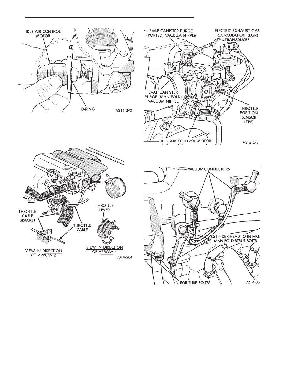
(4) Remove throttle cable (Fig. 6). Remove wiring
harness from throttle cable bracket and intake man-
ifold water tube.
(5) Disconnect idle air control motor and throttle
position sensor (TPS) electrical connectors (Fig. 7).
Refer to Idle Air Control Motor and Throttle Position
Sensor in this section.
(6) Remove vacuum hose harness from throttle
body (Fig. 7).
(7) Remove PCV and brake booster vacuum hoses
from air intake plenum.
(8) Remove EGR tube to intake manifold flange
bolts (Fig. 8).
(9) Remove vacuum harness connectors from in-
take plenum (Fig. 8).
(10) Remove cylinder head to intake plenum strut
(Fig. 8).
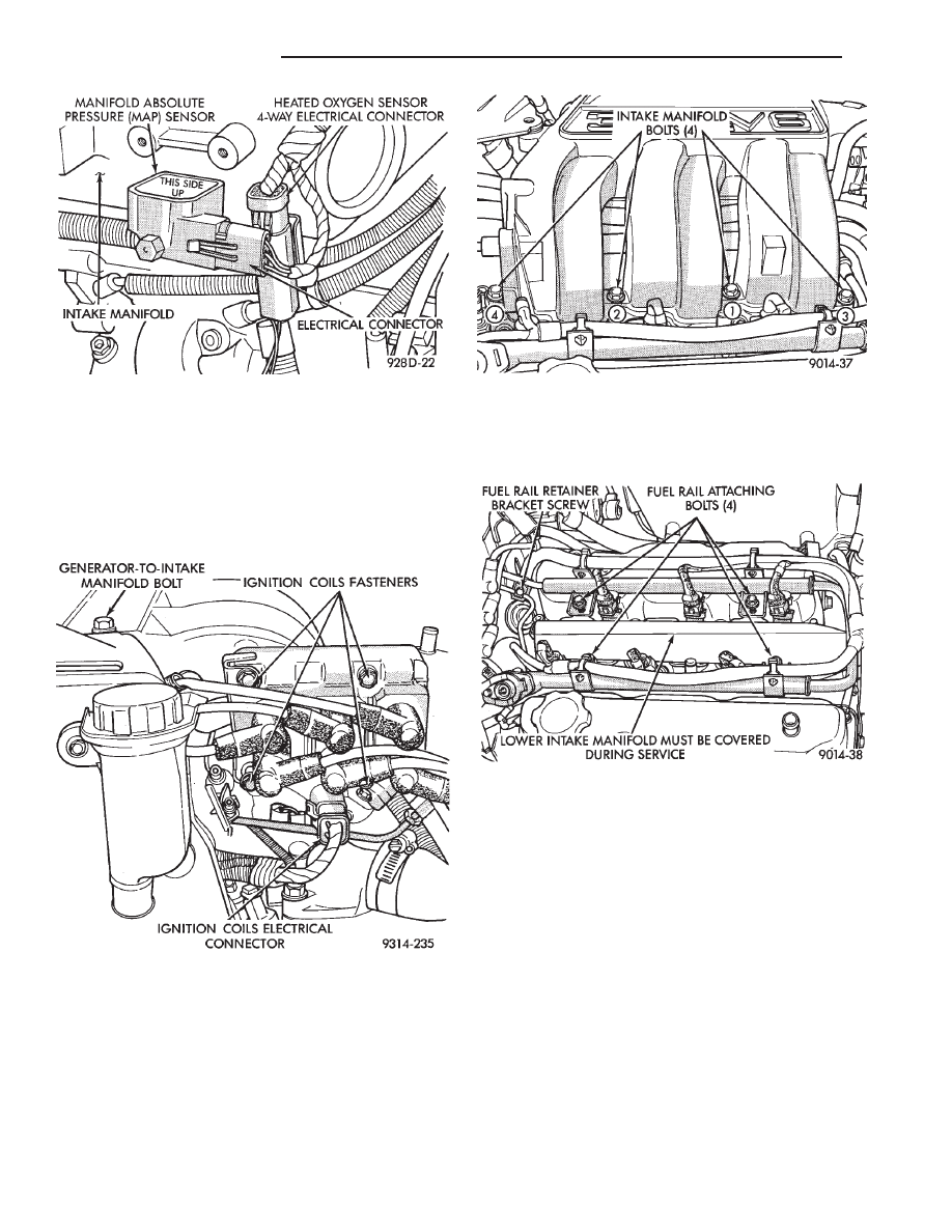
(11) Disconnect electrical connectors from the MAP
sensor and heated oxygen sensor electrical connec-
tion. Remove the engine mounted ground strap (Fig.
9).
WARNING:
WRAP
A
SHOP
TOWEL
AROUND
HOSES TO CATCH ANY GASOLINE SPILLAGE.
Fig. 5 Servicing Idle Air Control Motor
Fig. 6 Throttle Cable Attachment
Fig. 7 Electrical and Vacuum Connection to Throttle
Body
Fig. 8 EGR Tube
Ä
FUEL SYSTEMS
14 - 171
(12) Remove the fuel hose quick connect fittings
from the chassis tubes. Refer to Fuel Hoses, Clamps
and Quick Connect Fittings in the Fuel Delivery
Section of this Group. Place a shop towel under the
connections to absorb any fuel spilled. fittings.
(13) Remove direct ignition system (DIS) coils and
generator bracket to intake manifold bolt (Fig. 10).
(14) Remove intake mounting manifold bolts and
rotate manifold back over rear valve cover (Fig. 11).
(15) Cover intake manifold with suitable cover when
servicing (Fig. 12).
(16) Remove vacuum harness connector from Fuel
Pressure Regulator.
(17) Remove fuel tube retainer bracket screw and
fuel rail attaching bolts (Fig. 12). Spread the retainer
bracket to allow fuel tube removal clearance.
(18) Remove fuel rail injector wiring clip from the
generator bracket (Fig. 13).
(19) Disconnect camshaft position sensor, coolant
temperature sensor, and engine temperature sensors
(Fig. 13).
(20) Remove fuel rail. Be careful not to damage
the injector O-rings upon removal from their ports
(Fig. 14).
INSTALLATION
(1) Ensure
injector
holes
are
clean.
Replace
O-rings if damaged.
(2) Lubricate injector O-rings with a drop of clean
engine oil to ease installation.
(3) Put the tip of each injector into their ports.
Push the assembly into place until the injectors are
seated in the ports (Fig. 14).
(4) Install the fuel rail mounting bolts. Tighten
bolts to 22 N
Im (200 in. lbs.) torque (Fig. 12).
Fig. 11 Intake Manifold Bolts
Fig. 12 Fuel Rail Attaching Bolts
Fig. 9 MAP Sensor Electrical Connector
Fig. 10 Ignition Coils
14 - 172
FUEL SYSTEMS
Ä
Нет комментариевНе стесняйтесь поделиться с нами вашим ценным мнением.
Текст