Chrysler Le Baron, Dodge Dynasty, Plymouth Acclaim. Manual — part 290

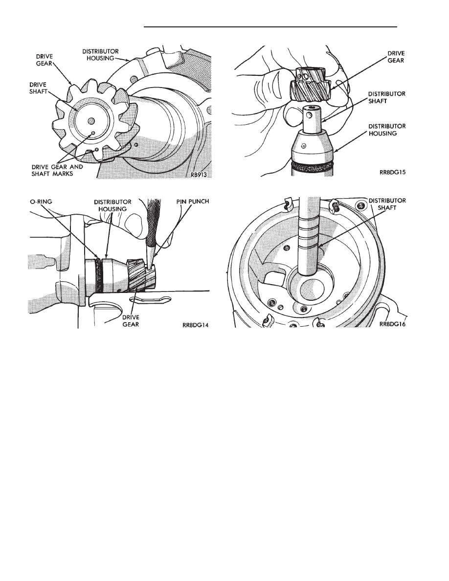
(10) Make reassembly alignment marks on gear
and shaft (Figs. 29 and 30).
(11) With a pin punch drive out distributor drive
gear roll pin (Fig. 31).
(12) Remove distributor drive gear (Fig. 32).
(13) Remove distributor shaft and bearing assem-
bly (Fig. 33).
(14) To reassemble, reverse preceding procedure.
Refer to Fig. 34.
Fig. 24 Disk Assembly Screw
Fig. 25 Disk and Spacers Installed
Fig. 26 Disk and Spacers
Fig. 27 Photo Optic Sensing Unit Assembly and
Bushing
Fig. 28 Bearing Retainer Screws
Fig. 29 Marking Drive Gear and Shaft
Ä
IGNITION SYSTEMS
8D - 21
MANIFOLD ABSOLUTE PRESSURE (MAP) SENSOR
SERVICE—2.5L TBI AND 3.0L ENGINES
(1) Remove vacuum hose and remove mounting
screws from sensor (Fig. 35, 36 and 37).
(2) Remove wiring harness and remove sensor.
(3) Reverse the above procedure for installation.
Check that vacuum hose is attached to vacuum
source.
Fig. 30 Marks on Drive Gear and Shaft
Fig. 31 Drive Gear Roll Pin
Fig. 32 Drive Gear
Fig. 33 Distributor Shaft
8D - 22
IGNITION SYSTEMS
Ä
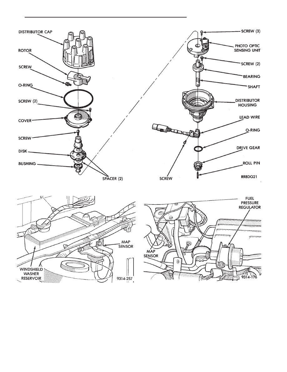
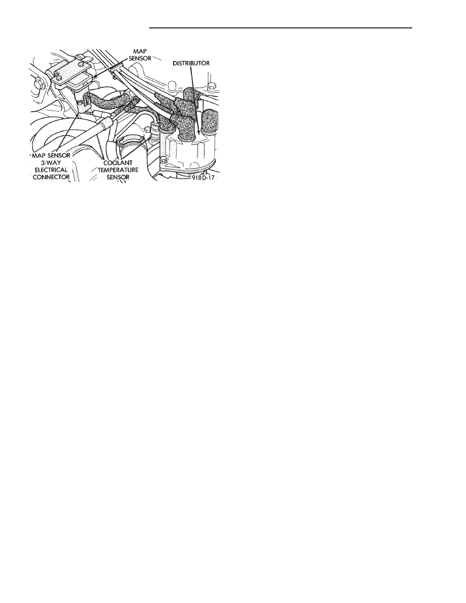
Fig. 35 Manifold Absolute Pressure (MAP)
Sensor—2.2L and 2.5L TBI Engines
Fig. 36 Manifold Absolute Pressure (MAP)
Sensor—2.5L MPI (Flexible Fuel AA-Body) Engines
Fig. 34 Distributor—3.0L Engine
Ä
IGNITION SYSTEMS
8D - 23
2.2L TURBO III, 3.3L AND 3.8L IGNITION SYSTEM—SYSTEM OPERATION
INDEX
page
page
Auto Shutdown (ASD) Relay and Fuel Pump
Relay
. . . . . . . . . . . . . . . . . . . . . . . . . . . . . . . . 32
Camshaft Position Sensor
. . . . . . . . . . . . . . . . . . 28
Coolant Temperature Sensor
. . . . . . . . . . . . . . . . 32
Crankshaft Position Sensor
. . . . . . . . . . . . . . . . . 29
General Information
. . . . . . . . . . . . . . . . . . . . . . . 24
Ignition Coil
. . . . . . . . . . . . . . . . . . . . . . . . . . . . . 31
Knock Sensor—Turbo III Engine
. . . . . . . . . . . . . 32
Manifold Absolute Pressure (MAP) Sensor
. . . . . 32
Powertrain Control Module (PCM)
. . . . . . . . . . . . 24
Spark Plug Cables
. . . . . . . . . . . . . . . . . . . . . . . 25
Spark Plugs
. . . . . . . . . . . . . . . . . . . . . . . . . . . . 26
GENERAL INFORMATION
This section describes the ignition systems for 2.2L
Turbo III, 3.3L and 3.8L engines.
The Fuel Injection sections of Group 14 describe On
Board Diagnostics.
Group 0, Lubrication and Maintenance, contains
general maintenance information for ignition related
items. The Owner’s Manual also contains maintenance
information.
2.2L Turbo III, 3.3L and 3.8L engines uses a
fixed ignition timing system. Basic ignition tim-
ing is not adjustable. All spark advance is deter-
mined by the powertrain control module (PCM).
The ignition system does not use a distributor. The
system is referred to as the Direct Ignition System. The
system’s three main components are the coil pack,
crankshaft position sensor, and camshaft position sen-
sor. The crankshaft and camshaft sensors are hall
effect devices.
The camshaft position and crankshaft position sen-
sors generate pulses that are the inputs sent to the
PCM. The PCM interprets crankshaft and camshaft
position from these sensors. The PCM uses crankshaft
position sensor input to determine ignition timing. The
PCM determines injector sequence from the camshaft
position sensor.
The camshaft position sensor determines when a
slot in the camshaft gear passes beneath it (Fig. 1 or
Fig. 2). The crankshaft position sensor determines
when a window in the drive plate passes under it
(Fig. 3 or Fig. 4). When metal aligns with the sensor,
voltage goes low (less than 0.5 volts). When a notch
aligns with the sensor, voltage spikes high (5.0
volts). As a group of notches pass under the sensor,
the voltage switches from low (metal) to high (notch)
then back to low.
FIRING ORDER
The firing order of the 2.2L Turbo III engine direct
ignition system is 1-3-4-2 (Fig. 5). The firing order of
the 3.3L and 3.8L engines direct ignition system is
1-2-3-4-5-6 (Fig. 6).
POWERTRAIN CONTROL MODULE (PCM)
The ignition system is regulated by the powertrain
control module (PCM) (Fig. 7). The PCM supplies
battery voltage to the ignition coil through the Auto
Shutdown (ASD) Relay. The PCM also controls
ground circuit for the ignition coil. By switching the
ground path for the coil on and off, the PCM adjusts
ignition timing to meet changing engine operating
conditions.
Fig. 37 Manifold Absolute Pressure (MAP)
Sensor—3.0L Engine
8D - 24
IGNITION SYSTEMS
Ä
Нет комментариевНе стесняйтесь поделиться с нами вашим ценным мнением.
Текст