Chrysler Le Baron, Dodge Dynasty, Plymouth Acclaim. Manual — part 81

(6) Disconnect tie rod end from steering arm with
Puller Special, Tool C-3894-A (Fig. 5).
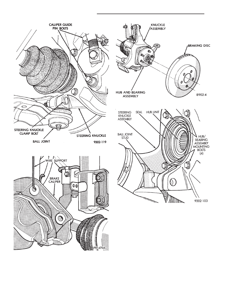
(7) Remove clamp bolt securing the ball joint stud
into the steering knuckle (Fig. 6).
(8) Remove caliper guide pin bolts (Fig. 6) and sepa-
rate caliper assembly from braking disc. Support
caliper with wire hook and not by hydraulic
hose. (Fig. 7) Remove braking disc from hub and
bearing assembly (Fig. 8).
(9) Separate the steering knuckle assembly from the
ball joint stud. Pull knuckle assembly out and away
from driveshaft (Fig. 9).
Care must be taken not to separate the inner
C/V joint during this operation. Do not allow
driveshaft to hang by inner C/V joint, driveshaft
must be supported.
(10) Remove the four hub and bearing assembly
mounting bolts from rear of steering knuckle (Fig. 9).
(11) Remove the hub and bearing assembly from
the steering knuckle (Fig. 10). Replacement of the
grease seal is recommended whenever this ser-
vice is performed.
INSTALLATION
CAUTION: All steering knuckle and bearing mounting
surfaces must be smooth and completely free of
foreign material or nicks.
(1) Install new front hub and bearing assembly into
the steering knuckle. Tighten the hub and bearing
assembly to steering knuckle attaching bolts (Fig. 9), in
a criss-cross pattern to 65 N
Im (45 ft. lbs.) torque.
Fig. 2 Front Hub And Bearing Assembly Mounting
Fig. 3 Remove Cotter Pin, Nut Lock, & Spring
Washer
Fig. 4 Loosen Hub Nut
Fig. 5 Disconnect Tie Rod End
Ä
SUSPENSION AND DRIVESHAFTS
2 - 21
(2) Position new hub and bearing assembly seal in
recess of the steering knuckle (Fig. 11). Assemble In-
staller, Special Tool C-4698. Tool is provided with a
handle and dual purpose drive head for installing
seal into knuckle and (head reversed) for installing
wear sleeve onto C/V joint housing.
(3) Using Special Tool C-4698 (Fig. 11) install the
hub and bearing seal, until fully seated into the
steering knuckle recess.
CAUTION: During any required service procedures
that require steering knuckle and driveshaft to be
separated. Both seal and wear sleeve must be
throughly cleaned and lubricated.
(4) Lubricate the FULL circumference of the bearing
seal (and wear sleeve) as shown in (Fig. 12). With Mo-
par
t Multi-Purpose Lubricant, or equivalent.
Fig. 8 Remove or Install Braking Disc
Fig. 9 Separate Ball Joint Stud from Steering
Knuckle
Fig. 6 Remove Clamp Bolt and Caliper Guide Pins
Fig. 7 Supporting Brake Caliper
2 - 22
SUSPENSION AND DRIVESHAFTS
Ä
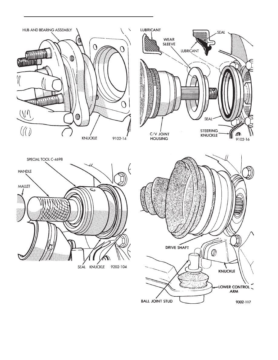
(5) Insert driveshaft through hub and bearing as-
sembly, while installing steering knuckle assembly
on lower control arm ball joint stud (Fig. 13).
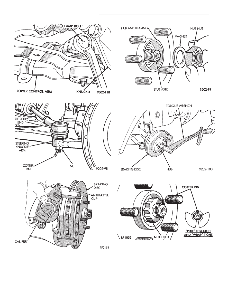
(6) Install original (or equivalent) ball joint to
knuckle clamp bolt (Fig. 14) into steering knuckle.
Tighten clamp bolt to 145 N
Im (105 ft. lbs.) torque.
(7) Install tie rod end into steering knuckle arm
(Fig. 15). Tighten tie rod to steering knuckle arm at-
taching nut to 47 N
Im (35 ft. lbs.) torque and install
cotter pin.
(8) Install braking disc (Fig. 8).
(9) Carefully lower brake caliper assembly over
braking disc (Fig. 16).
(10) Install brake caliper assembly guide pin bolts.
Tighten guide pin bolts to 25-35 N
Im (18-26 ft. lbs.)
Fig. 10 Separate Hub and Bearing Assembly from
Knuckle
Fig. 11 Bearing Seal Installation
Fig. 12 Seal and Wear Sleeve Lubrication
Fig. 13 Installing Knuckle Assembly
Ä
SUSPENSION AND DRIVESHAFTS
2 - 23
torque. When installing guide pins, use extreme
caution not to cross the threads.
(11) Clean all foreign matter from the threads of the
stub axle (Fig. 17). Install the washer and hub nut (Fig.
17) onto the threads of the stub axle and tighten nut.
(12) With brakes applied, tighten front hub nut to
(244 N
Im) 180 ft. lbs. torque (Fig. 18).
(13) Install spring washer, nut lock, and new cot-
ter pin. Wrap cotter pin prongs tightly around nut
lock (Fig. 19).
Install wheel and tire assembly. Tighten wheel
nuts to 129 N
Im (95 ft. lbs.) torque.
Fig. 15 Install Tie Rod End
Fig. 16 Installing Family Caliper
Fig. 17 Install Washer and Hub Nut
Fig. 18 Tighten Hub Nut
Fig. 19 Install Spring Washer, Nut Lock, & Cotter
Pin
Fig. 14 Tighten Clamp Bolt
2 - 24
SUSPENSION AND DRIVESHAFTS
Ä
Нет комментариевНе стесняйтесь поделиться с нами вашим ценным мнением.
Текст