Chrysler Le Baron, Dodge Dynasty, Plymouth Acclaim. Manual — part 125
If screen (c) appears, the transmission control mod-
ule has completed its break-in status program. Press
the enter key on the DRB II scan tool key pad to return
the status to the start of break-in.
(9) After pressing the enter key a second time in step
8 a screen will appear that says ‘‘RESET LU CLUTCH
ARE YOU SURE ?’’. Press the enter key on the DRB II
scan tool key pad. The DRB II scan tool will then carry
out the reset command.
(10) After the DRB II scan tool completes the reset
command, a screen will appear saying ‘‘LU Clutch
Break-in Status has been RESET to Start’’. This screen
will indicate that the reset procedure has been success-
fully completed.
(11) Disconnect the DRB II scan tool from the blue
CCD Bus connector.
TRANSAXLE RECONDITION
Tag all clutch pack assemblies, as they are
removed, for reassembly identification.
CAUTION: Do not intermix clutch discs or plates as
the unit might then fail.
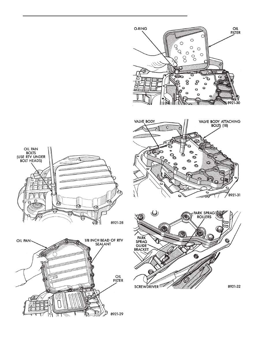
Fig. 1 Oil Pan Bolts
Fig. 2 Oil Pan
Fig. 3 Oil Filter
Fig. 4 Valve Body Attaching Bolts
Fig. 5 Push Park Rod Rollers from Guide Bracket
Ä
TRANSAXLE
21 - 105
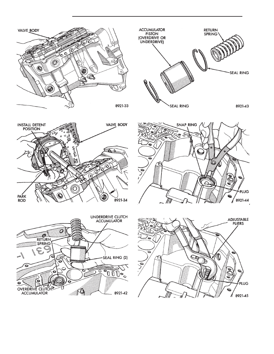
Fig. 6 Remove or Install Valve Body
Fig. 7 Valve Body Removed
Fig. 8 Accumulators
Fig. 9 Accumulator
Fig. 10 Low/Reverse Accumulator Snap Ring
Fig. 11 Low/Reverse Accumulator Plug (Cover)
21 - 106
TRANSAXLE
Ä
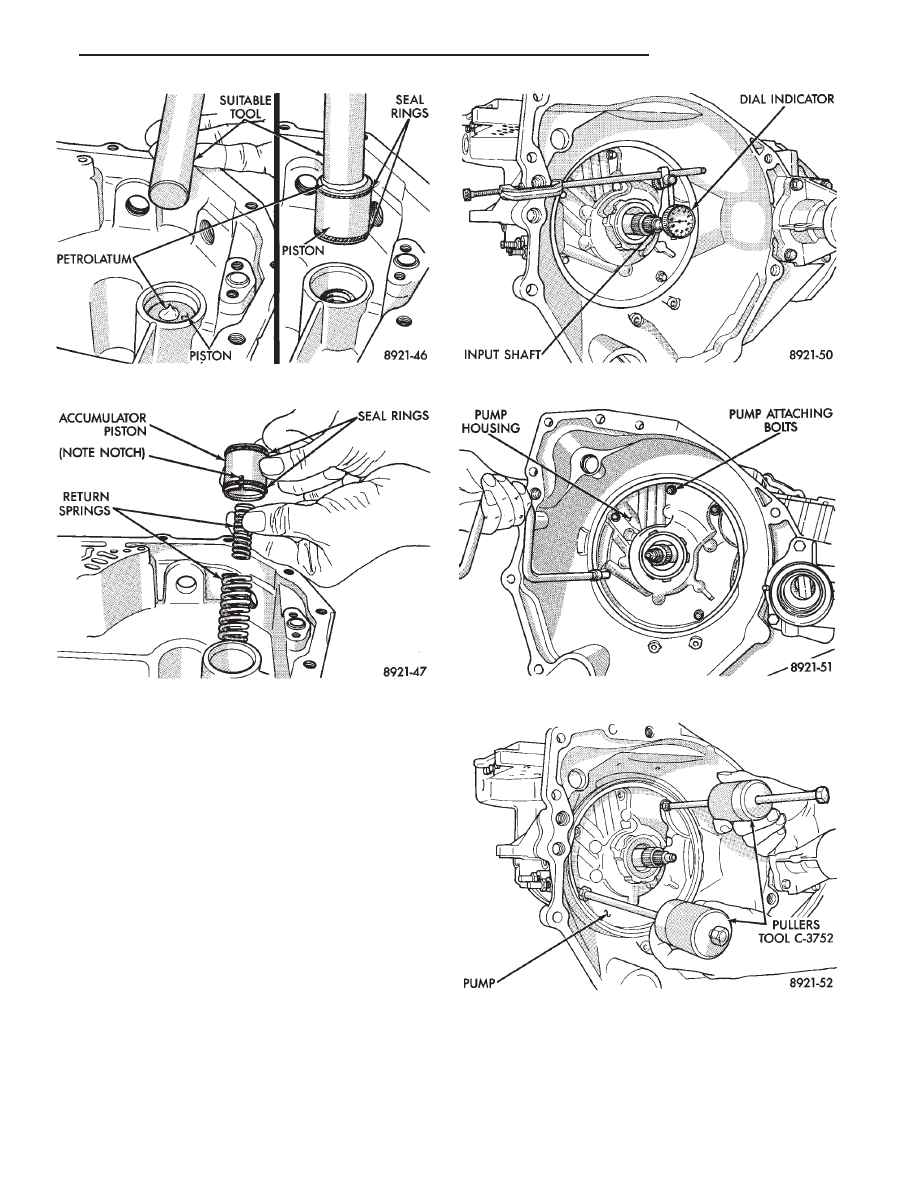
Measuring input shaft end play before disassembly
will usually indicate when a #4 thrust plate change
is required, (except when major parts are replaced).
The #4 thrust plate is located behind the overdrive
clutch hub.
Attach a dial indicator to transaxle bell housing
with its plunger seated against end of input shaft
(Fig. 14).
Move input shaft in and out to obtain end play
reading. End play specifications are .13 to .64 mm
(.005 to .025 inch).
Record indicator reading for reference when reas-
sembling the transaxle.
Fig. 12 Low/Reverse Accumulator Piston
Fig. 13 Low/Reverse Accumulator
Fig. 14 Measure Input Shaft End Play
Fig. 15 Pump Attaching Bolts
Fig. 16 Install Tool C-3752
Ä
TRANSAXLE
21 - 107
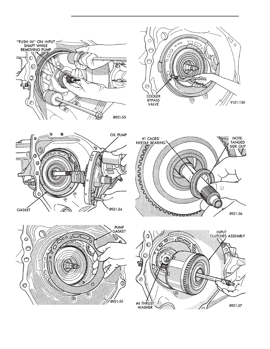
CAUTION: Be sure input speed sensor is removed
before removing oil pump.
CAUTION:The cooler bypass valve must be re-
placed if a transaxle failure has occurred. Do not re-
use old valve or attempt to clean old valve. When
installing bypass valve, insert with O-ring end to-
wards rear of case.
Fig. 17 Remove Oil Pump
Fig. 18 Oil Pump Removed
Fig. 19 Oil Pump Gasket
Fig. 20 Remove Bypass Valve
Fig. 21 No.1 Caged Needle Bearing
Fig. 22 Input Clutches Assembly
21 - 108
TRANSAXLE
Ä
Нет комментариевНе стесняйтесь поделиться с нами вашим ценным мнением.
Текст