Chrysler Le Baron, Dodge Dynasty, Plymouth Acclaim. Manual — part 242
Lamp Relay opens the Anti-Lock Warning Lamp Re-
lay switch. This breaks the ground path to the Am-
ber Anti-Lock Warning Lamp and the light is turned
off.
The (CAB) by itself, also has the ability to turn on
the Amber Anti-Lock Warning Lamp. The (CAB) can
turn on the Amber Anti-Lock Warning Lamp by pro-
viding a ground at pin 15.
ANTI-LOCK WARNING LAMP ON
System Relay and Anti-Lock Warning Lamp
Relay De-Energized.
When the Amber Anti-Lock Warning Lamp is on,
there is no electrical current flow from the (CAB) at
pin 57. The System Relay coil is NOT energized. No
electrical current flows to pin 47 and 41 (modulator
valve power), or to the Anti-Lock Warning Lamp Re-
lay coil. Thus, the Amber Anti-Lock Warning Lamp
is not energized. The Amber Anti-Lock Warning
Lamp is grounded through the Anti-Lock Warning
Lamp Relay contacts. The Amber Anti-Lock Warning
Lamp is turned on.
HYDRAULIC CIRCUITS AND VALVE OPERATION
Through the following operation descriptions and
diagrams. The function of the various hydraulic con-
trol valves in the ABS system will be described. The
fluid control valves mentioned below, control the flow
of pressurized brake fluid to the wheel brakes during
the different modes of Anti-Lock braking.
For explanation purposes we will assume all speed
sensors are sending the same wheel speed informa-
tion, requiring the same hydraulic fluid modulation
at the same rate.
NORMAL BRAKING
ISOLATION VALVES
Open to primary and secondary master cylinder
fluid supply (Fig. 1)
BUILD/DECAY VALVES
Closed (Fig. 1)
The brake pedal is applied. The travel of the brake
pedal closes primary and secondary circuits from the
master cylinder fluid supply. Brake fluid from the
primary and secondary circuits flows through the
open isolation valves, through the build/decay valves
to the wheel brakes.
ABS BRAKING-BUILD PRESSURE
ISOLATION VALVES
Closed, isolating wheel brakes from master cylin-
der primary and secondary fluid supply. Through
open build valves (Fig. 2).
BUILD/DECAY VALVES
Open (Fig. 2)
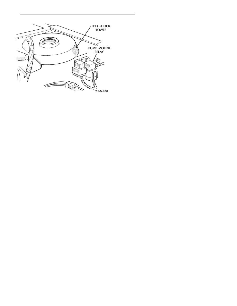
Fig. 11 Pump Motor Relay W/O Power Distribution
Center
Ä
ANTI-LOCK 6 BRAKE SYSTEM
5 - 121
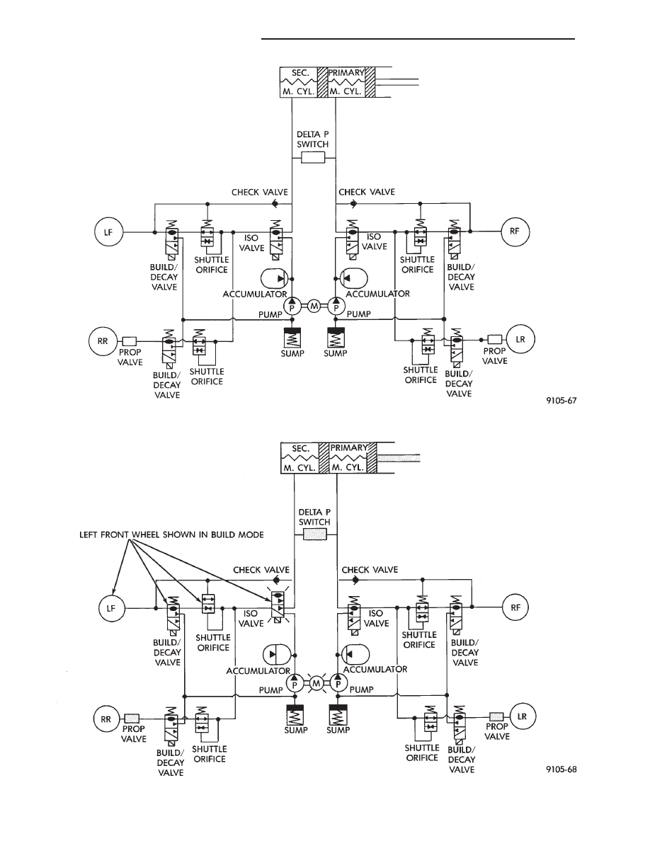
Fig. 1 Normal Braking - Hydraulic Control
Fig. 2 Build Pressure - Hydraulic Control
5 - 122
ANTI-LOCK 6 BRAKE SYSTEM
Ä
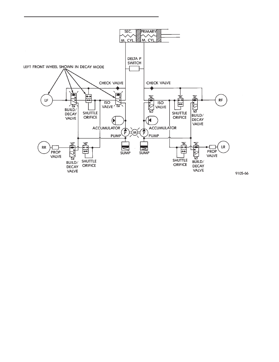
ABS BRAKING-DECAY PRESSURE
ISOLATION VALVES
Closed, isolating the wheel brakes from the master
cylinder primary and secondary fluid supplies (Fig.
3)
BUILD/DECAY VALVES
Open, allowing release of fluid pressure through
decay valve to the fluid reservoir. Which gets
pumped into the accumulator for the build pressure
cycle (Fig. 3).
ABS BRAKE SYSTEM DIAGNOSIS
GENERAL INFORMATION
WARNING: SOME OPERATIONS IN THIS SECTION
REQUIRE THAT HYDRAULIC TUBES, HOSES AND
FITTINGS BE DISCONNECTED FOR INSPECTION
OR TESTING PURPOSES.
CAUTION: REVIEW THIS ENTIRE SECTION PRIOR
TO PERFORMING ANY MECHANICAL WORK ON A
VEHICLE EQUIPPED WITH THE BENDIX ANTI-LOCK
6 BRAKE SYSTEM. THIS SECTION CONTAINS IN-
FORMATION ON PRECAUTIONS PERTAINING TO
POTENTIAL COMPONENT DAMAGE, VEHICLE DAM-
AGE AND PERSONAL INJURY WHICH COULD RE-
SULT
WHEN
SERVICING
AN
ABS
EQUIPPED
VEHICLE.
CAUTION: Certain components of the Anti-Lock
Brake System (ABS) are not intended to be serviced
individually. Attempting to remove or disconnect
certain system components, may result in personal
injury and/or improper system operation. Only
those components with approved removal and in-
stallation procedures in this manual should be ser-
viced.
This section contains information necessary to di-
agnosis mechanical conditions which can affect oper-
ation of the Bendix Anti-Lock 6 Brake System.
Specifically, this section should be used to help diag-
nose mechanical conditions which result in any of
the following:
(1) Anti-Lock Warning Lamp turned on.
(2) Brakes Lock on Hard Application
Diagnosis of conditions which are obviously me-
chanical in nature. Such as brake noise, brake pulsa-
tion, lack of power assist, turning on of the Red
Brake Warning Lamp or vehicle vibration during
normal braking. Should be directed to Group 5
Brakes in this service manual. This also pertains to
problems involving the parking brake system.
Fig. 3 Decay Pressure - Hydraulic Control
Ä
ANTI-LOCK 6 BRAKE SYSTEM
5 - 123
In order to effectively diagnose an Anti-Lock Brake
System (ABS) condition. It is important to read Anti-
Lock Brake System Description. And to follow the
diagnostic procedures outlined in this section.
Many conditions that generate customer complaints
may be normal operating conditions, but are judged to
be a problem due to not being familiar with the ABS
system. These conditions can be recognized without
performing extensive diagnostic work. Given adequate
understanding of the operating principles and perfor-
mance characteristics of the ABS system. See Section 1
of this manual to familiarize yourself with the operat-
ing principles of the ABS system.
DEFINITIONS
Several abbreviations are used in this manual. They
are presented here for reference.
• CAB—Controller Anti-Lock Brake
• ABS—Anti-Lock Brake System
• PSI—Pounds per Square Inch (pressure)
• WSS—Wheel Speed Sensor
ABS COMPUTER SYSTEM SERVICE PRECAUTIONS
The ABS system uses an electronic control module,
the (CAB). This module is designed to withstand nor-
mal current draws associated with vehicle operation.
However care must be taken to avoid overloading the
(CAB) circuits. In testing for open or short circuits,
do not ground or apply voltage to any of the
circuits unless instructed to do so by the appro-
priate diagnostic procedure. These circuits should
only be tested using a high impedance multi-meter,
special tools or the DRB II tester as described in this
section. Power should never be removed or applied to
any control module with the ignition in the ON posi-
tion. Before removing or connecting battery cables,
fuses, or connectors, always turn the ignition to the
OFF position.
ABS GENERAL SERVICE PRECAUTIONS
TEST DRIVING ABS COMPLAINT VEHICLES
Most ABS complaints will require a test drive as a
part of the diagnostic procedure. The purpose of the
test drive is to duplicate the condition.
Remember conditions that result in the turn-
ing on of the Red Brake Warning Lamp may
indicate reduced braking ability. The following
procedure should be used to test drive an ABS
complaint vehicle.
Before test driving a brake complaint vehicle, note
whether the Red or Amber Brake Warning Lamp is
turned on. If it is the Red Brake Warning Lamp, refer
to the standard brake, Control Valves Section in the
brake group of this manual. If the Amber Anti-Lock
Warning light was/is on, read record and erase the
fault. While the Amber ABS Warning Lamp is on the
ABS system is not functional. When the Am-
ber Anti-Lock Warning Lamp is on only the Anti-Lock
function of the brake system if affected. The standard
brake system and the ability to stop the car is not be
affected if only the Amber Anti-Lock Warning Lamp is
on.
(1) Turn the key to the off position and then back to
the on position. Note whether the Amber ABS Warning
Lamp continues to stay on. If it does refer to the 1993
M.Y. Bendix Anti-Lock 6 Diagnostic Manual for the
required test procedures.
(2) If the Amber ABS Warning Lamp goes out, shift
into gear and drive the car to a speed of 5 mph to
complete the ABS start up cycle. If at this time the
Amber ABS Warning Lamp goes on refer to the Bendix
Anti-Lock 6 Diagnostic Manual.
(3) If the Amber ABS Warning Lamp remains OUT,
drive the vehicle a short distance. During this test
drive be sure that the vehicle achieves at least 25 mph.
Brake to at least one complete stop and again acceler-
ate to 25 mph.
(4) If a functional problem with the A.B.S. system is
determined while test driving a vehicle. Refer to the
Bendix Anti-Lock 6 Diagnostics Manual for required
test procedures and proper use of the DRB II tester.
ABS BRAKE SYSTEM ON VEHICLE SERVICE
The following are general precautions which
should be observed when servicing and diagnos-
ing the ABS system and/or other vehicle systems.
Failure to observe these precautions may result
in ABS system damage.
(1) If welding work is to be performed on a vehicle
using an arc welder, the (CAB) should be disconnected
before the welding operation begins.
(2) The (CAB) and modulator assembly 10 way con-
nector should never be connected or disconnected with
the ignition in the on position.
(3) Some components of the ABS system are not
serviced separately and must be serviced as complete
assemblies. Do not disassemble any component which
is designated as non-serviceable.
CAUTION: Brake fluid will damage painted surfaces.
If brake fluid is spilled on any painted surfaces, wash
off with water immediately.
WHEEL SPEED SENSOR CABLES
Proper installation of the Wheel Speed Sensor Cables
is critical to continued system operation. Be sure that
cables are installed, routed and clipped properly. Fail-
ure to install speed sensor cables as shown in the on
car service section of this manual. May result in
contact with moving parts or over extension of cables,
resulting in component failure and an open circuit.
5 - 124
ANTI-LOCK 6 BRAKE SYSTEM
Ä
Нет комментариевНе стесняйтесь поделиться с нами вашим ценным мнением.
Текст