Chrysler Le Baron, Dodge Dynasty, Plymouth Acclaim. Manual — part 91
A compression ball sleeve nut and sleeve for 3/16
inch tubing with ball sleeve connector and an inter-
nal pipe T-fitting. Can be used to attach the tubing
to the pressure gauge.
(3) Cycle ignition from OFF to ON.
(4) Apply a load to the rear of the vehicle (two as-
sistants or approximately 300-325 lbs.) to run com-
pressor and raise the vehicle.
(5) Remove the load applied in Step 4. Allow the
system to exhaust and lower the vehicle.
(6) When no more air can be exhausted, the gauge
should indicate 69 to 152 kPa (10 to 22 psi).
(7) Remove the pressure gauge and nylon tubing.
Attach the air line between the dryer and shock ab-
sorber. Repeat Steps 3, 4, and 5 to ensure system air
pressure is in the shocks.
LEAK CHECKS
(1) Repeat Residual Air Check Steps 1, 2, 3, and 4.
Allow the system to fill until gauge reads 483 to 621
kPa (70 to 90 psi).
If compressor is permitted to run until it reaches
its maximum output pressure, the vent solenoid
valve will function as a relief valve. The resulting
leak down, when compressor shuts off, will indicate a
false air leak.
(2) With load still applied, disconnect wire harness
connector from the control module, then remove ap-
plied load. Vehicle should rise. Cycle ignition switch
to OFF.
(3) Observe if pressure leaks down or holds steady
(wait approximately 15 minutes).
(A) If system will not inflate beyond 345 kPa (50
psi). A severe leak may be indicated. Check for a
pinched
pressure
line
between
compressor
and
shocks.
(B) The standard soap solution check procedure is
acceptable.
(C) If pressure holds steady, perform the diagnosis
procedures.
SYSTEM OPERATION
RAISING VEHICLE HEIGHT
When weight is added to the rear suspension. The
body of the vehicle is lowered, moving the height
sensor down.
This action will activate the internal time delay
circuit. After a time delay of 12 to 18 seconds. The
control module (CM) activates the ground circuit to
the compressor relay.
With the relay energized, the compressor motor
runs and air is sent through the system. As the
shock absorbers inflate, the body moves upward to a
corrected position. When the body reaches the correct
height, the control module (CM) stops the compressor
operation.
LOWERING VEHICLE HEIGHT
When the weight is removed from the vehicle. The
body moves upward, which allows the height sensor
to move upward and activate the internal time delay
circuit.
After a time delay of 12 to 18 seconds. The (CM)
activates the exhaust solenoid circuit. Air is ex-
hausted from the shock absorbers through the air
dryer and exhaust solenoid to the atmosphere.
As the body lowers, the height sensor is lowered to-
ward its original position. When the body reaches the
original vehicle height, the (CM) opens the exhaust
solenoid valve circuit.
COMPRESSOR PERFORMANCE TEST
This test can be performed on the vehicle. It is
used to evaluate compressor current draw, pressure
output, and leak down.
(1) Disconnect the compressor motor wiring har-
ness connector.
(2) Disconnect air line between dryer and right
shock absorber.
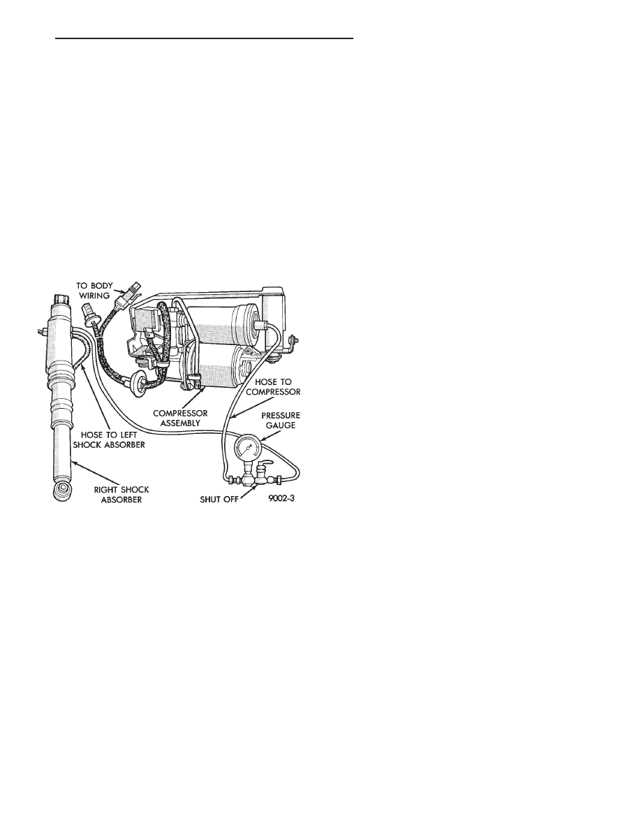
(3) Connect an air pressure gauge into the system
(Fig. 5).
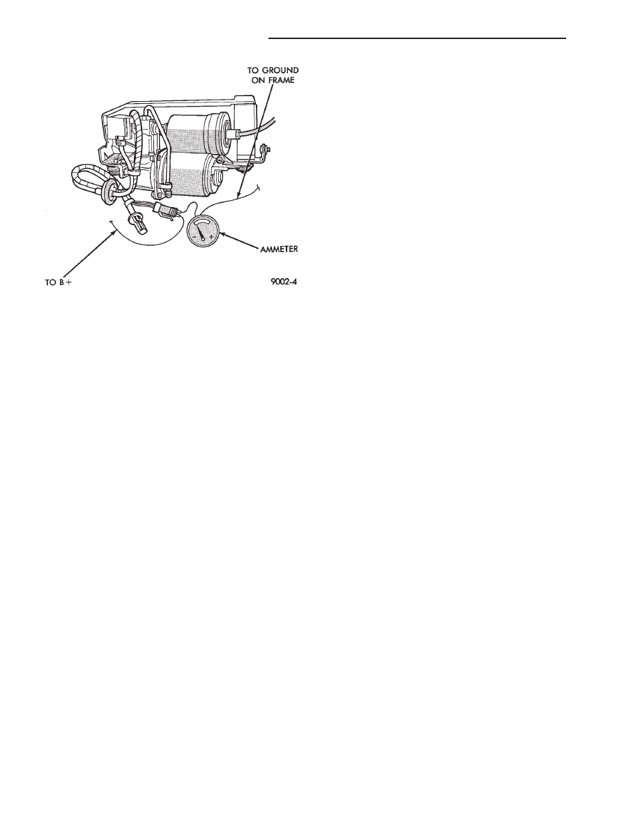
(4) Connect an ammeter in series between the red
wire terminal on compressor connector and a 12 volt
power source. Also, connect a ground wire from the
black wire terminal on the compressor connector to a
good ground on the frame (Fig. 6).
(5) If the current draw to the compressor motor ex-
ceeds 21 amperes, replace the compressor assembly.
(6) When the air pressure stabilizes at 827 kPa
(120 psi), disconnect the (+) wire lead from the con-
nector. Replace the compressor assembly if any of the
following conditions exists:
Fig. 5 Pressure Gauge Installed in System
Ä
SUSPENSION AND DRIVESHAFTS
2 - 61
• Air pressure leaks down below 621 kPa (90 psi),
before it remains steady.
• Output pressure builds up to less than 758 kPa
(110 psi) when it stabilizes.
If the compressor is allowed to run during this test
until it reaches its maximum output pressure of 1516
kPa (220 psi). The solenoid exhaust valve will act as
a pressure relief valve. The resulting leak-down, af-
ter the compressor is shut off, will indicate a false
leak.
SERVICE PROCEDURES
COMPRESSOR ASSEMBLY
REMOVAL
(1) Disconnect negative battery cable.
(2) Raise vehicle, see Hoisting, Group 0.
(3) Remove cover from compressor assembly. Re-
move air hose and electrical connectors (Figs. 1 and
2).
(4) Remove compressor assembly mounting bolts
and lower assembly from vehicle.
(5) Remove
mounting
bracket
bolts
and
slide
mounting bracket away from compressor.
INSTALLATION
(1) Slide mounting bracket on compressor and in-
stall bolts and tighten to 8 N
Im (70 in. lbs.) torque.
(2) Install compressor assembly to frame rail and
tighten bolts to 8 N
Im (70 in. lbs.) torque.
(3) Connect air hose and electrical connector to
compressor assembly.
(4) Install
cover
on
compressor
assembly
and
tighten bolts to 8 N
Im (70 in. lbs.) torque.
(5) Lower vehicle and connect negative battery ca-
ble.
(6) Check operation of the system.
Fig. 6 Compressor Current Draw Test
2 - 62
SUSPENSION AND DRIVESHAFTS
Ä
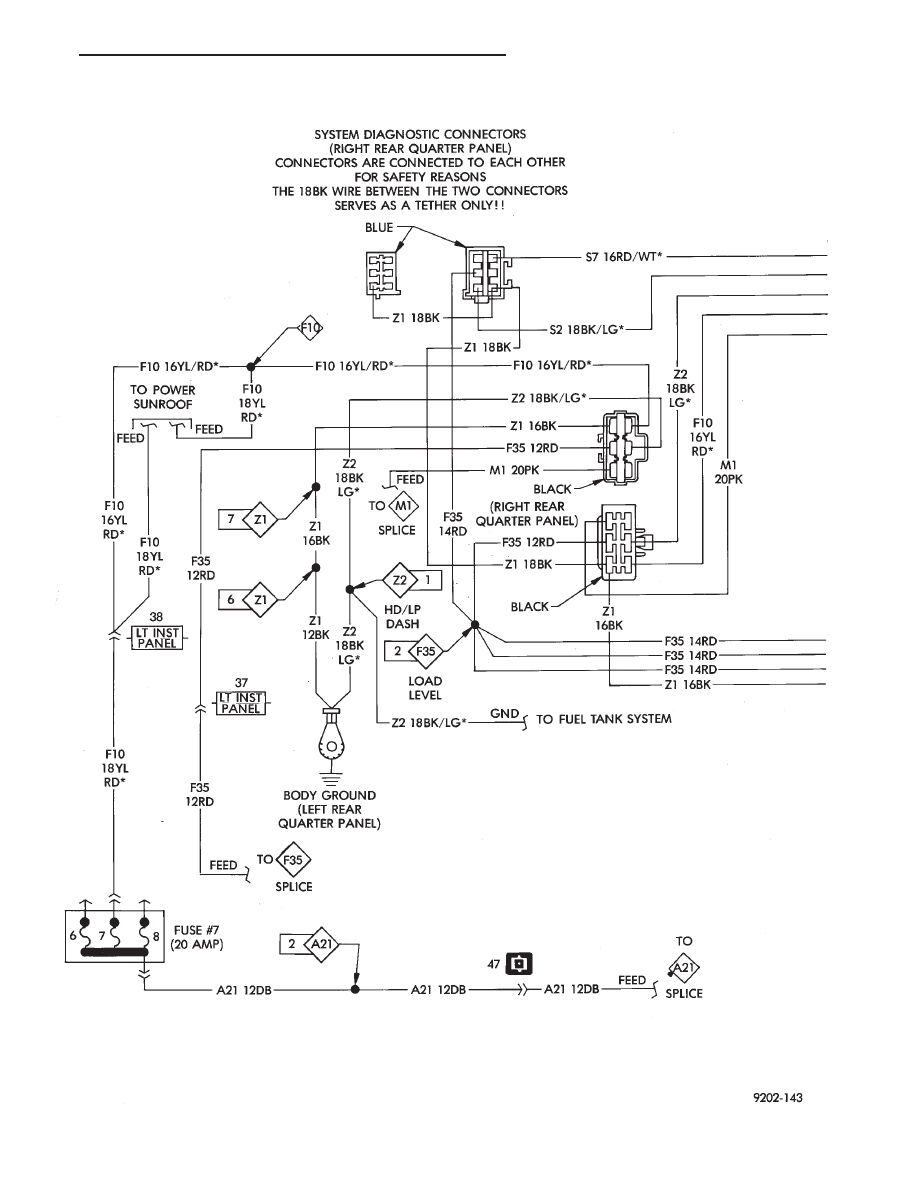
AUTOMATIC AIR LOAD LEVELING SYSTEM WIRING SCHEMATIC
Ä
SUSPENSION AND DRIVESHAFTS
2 - 63
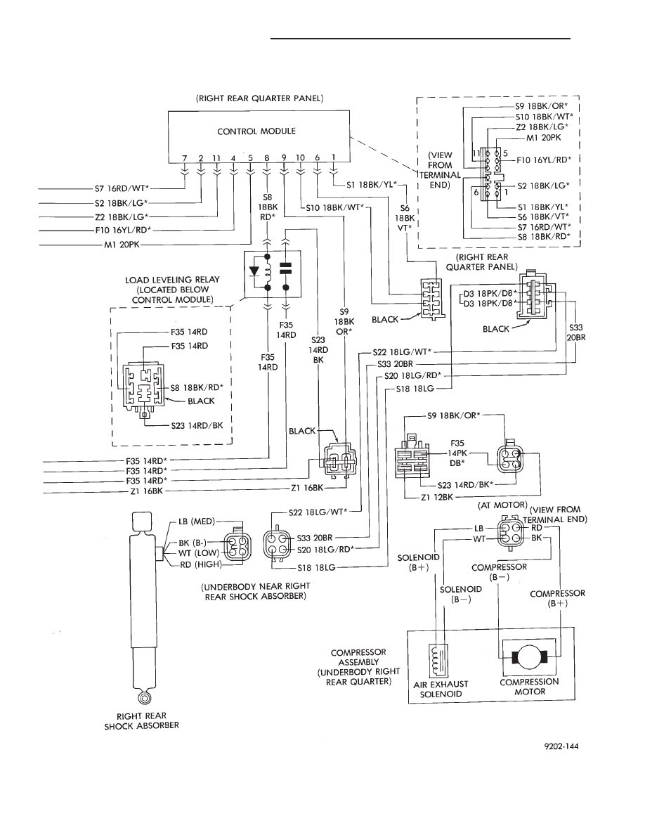
AUTOMATIC AIR LOAD LEVELING SYSTEM WIRING SCHEMATIC
2 - 64
SUSPENSION AND DRIVESHAFTS
Ä
Нет комментариевНе стесняйтесь поделиться с нами вашим ценным мнением.
Текст