Chrysler Le Baron, Dodge Dynasty, Plymouth Acclaim. Manual — part 576
CRANKSHAFT, INTERMEDIATE AND BALANCE SHAFT SERVICE
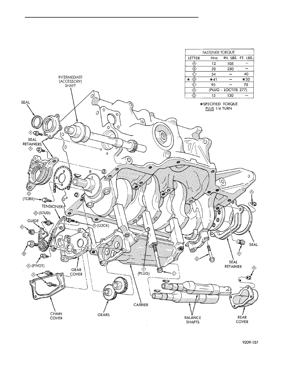
Fig. 1 Crankshaft Intermediate and Balance Shaft Assemblies and Oil Seals
Ä
2.2/2.5L ENGINE
9 - 41
CRANKSHAFT OIL SEALS SERVICE
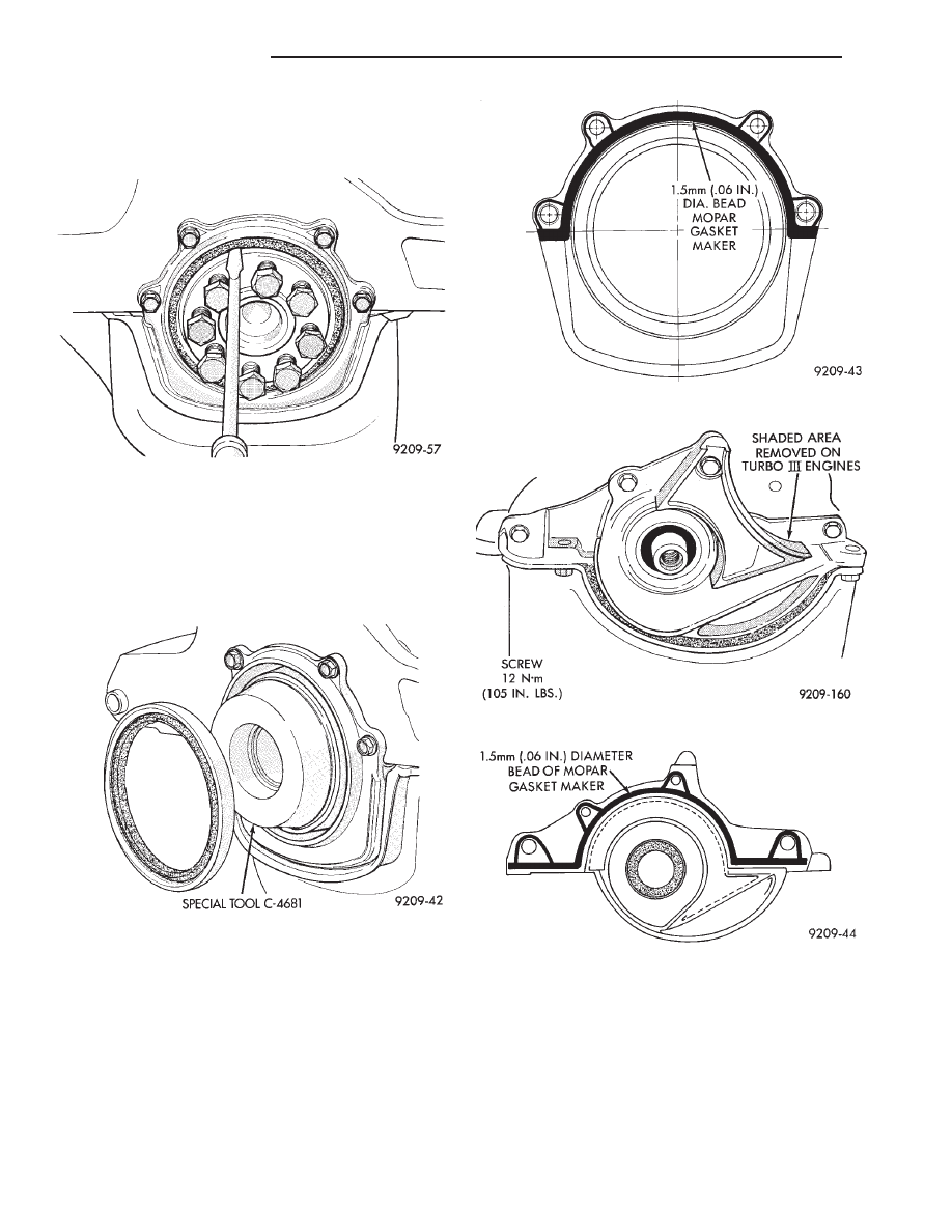
(1) Pry out rear seal with screwdriver. Be careful
not to nick or damage crankshaft flange seal surface
or retainer bore (Fig. 2).
(2) Place Special Tool C-4681 on crankshaft (Fig.
3).
(3) Lightly coat seal O.D. with Loctite Stud N’
Bearing Mount or equivalent.
(4) Place seal over Tool C-4681 and tap in place
with a plastic hammer.
REAR CRANKSHAFT SEAL RETAINER AND
OIL SEAL
When retainer removal is required, use Mopar Gas-
ket Maker applied as shown in (Fig. 4) to provide re-
tainer to block sealing during re-installation.
FRONT CRANKSHAFT SEAL RETAINER
See Timing System and Seals Section for timing
belt covers, belt, crankshaft sprocket and oil seals re-
moval and installation.
(1) Remove retainer screws (Fig. 5).
For reassembly Mopar Gasket Maker is applied to
the retainer as shown in (Fig. 6). This material cures
in the absence of air providing retainer to block seal-
ing.
(2) Install retainer and tighten screws to 12 N
Im
(105 in. lbs.).
Fig. 2 Removing Rear Crankshaft Oil Seal
Fig. 3 Installing Rear Crankshaft Oil Seal
Fig. 4 Rear Crankshaft Seal Retainer Sealing
Fig. 5 Front Crankshaft Oil Seal Retainer
Fig. 6 Front Crankshaft Seal Retainer Sealing
9 - 42
2.2/2.5L ENGINE
Ä
CRANKSHAFT SERVICE
CRANKSHAFT MAIN BEARINGS
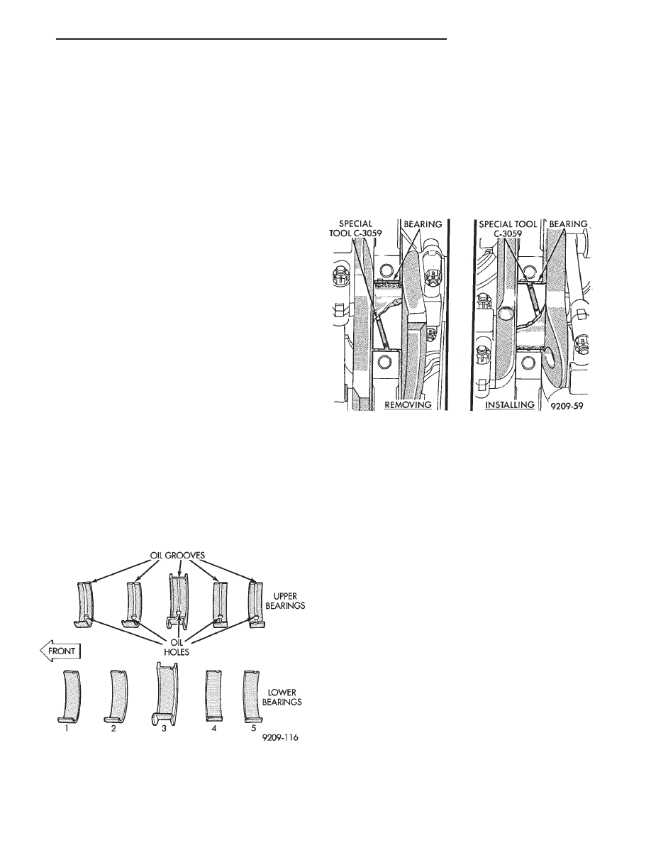
Bearing caps are not interchangeable and should
be marked at removal to insure correct assembly.
Upper and lower bearing halves are NOT inter-
changeable. Lower main bearing halves of 1, 2, 4 and
5 are interchangeable. Upper main bearing halves of
1, 2, 4 and 5 are interchangeable (Fig. 7).
CRANKSHAFT MAIN JOURNALS
The crankshaft journals should be checked for ex-
cessive wear, taper and scoring. Limits of taper or
out-of-round on any crankshaft journals should be
held to .025mm (.001 inch). Journal grinding should
not exceed .305mm (.012 inch) under the standard
journal diameter. Do NOT grind thrust faces of Num-
ber 3 main bearing. Do NOT nick crank pin or bear-
ing fillets. After grinding, remove rough edges from
crankshaft oil holes and clean out all passages.
CAUTION: With the nodular cast iron crankshafts
used it is important that the final paper or cloth pol-
ish after any journal regrind be in the same direc-
tion as normal rotation in the engine.
Upper and lower Number 3 bearing halves are
flanged to carry the crankshaft thrust loads and are
NOT interchangeable with any other bearing halves
in the engine (Fig. 7). All bearing cap bolts removed
during service procedures are to be cleaned and oiled
before installation. Bearing shells are available in
standard and the following undersized: 0.025mm
(.001 inch), .051mm (.002 inch), .076mm (.003 inch),
.254mm (.010 inch), and .305mm (.012 inch). Never
install an undersize bearing that will reduce clear-
ance below specifications.
MAIN BEARING SERVICE—CRANKSHAFT NOT
REMOVED
REMOVAL
(1) Remove oil pan and identify bearing caps before
removal.
(2) Remove bearing caps one at a time. Remove
upper half of bearing by inserting Special Main Bear-
ing Tool C-3059 (Fig. 8) into the oil hole of crankshaft.
(3) Slowly rotate crankshaft clockwise, forcing out
upper half of bearing shell.
INSTALLATION
Only one main bearing should be selectively
fitted while all other main bearing caps are prop-
erly tightened.
When installing a new upper bearing shell, slightly
chamfer the sharp edges from the plain side.
(1) Start bearing in place, and insert Main Bearing
Tool C-3059 into oil hole of crankshaft (Fig. 8).
(2) Slowly rotate crankshaft counter-clockwise slid-
ing the bearing into position. Remove Special Main
Bearing Tool C-3059.
CHECKING CRANKSHAFT END PLAY
(1) Mount a dial indicator to front of engine, locating
probe on nose of crankshaft (Fig. 9).
(2) Move crankshaft all the way to the rear of its
travel.
(3) Zero the dial indicator.
(4) Move crankshaft all the way to the front and read
the dial indicator. Refer to (Fig. 10) for specifications.
OPTIONAL CRANKSHAFT END PLAY CHECK
(1) Move crankshaft all the way to the rear of its
travel using a lever inserted between a main bearing
Fig. 7 Main Bearing Identification
Fig. 8 Removing and Installing Upper Main Bearing
With Special Tool C-3059
Ä
2.2/2.5L ENGINE
9 - 43
cap and a crankshaft cheek, using care not to dam-
age any bearing surface. Do not loosen main bearing
cap.
(2) Use a feeler gauge between number three
thrust bearing and machined crankshaft surface to
determine end play.
CRANKSHAFT BEARING CLEARANCE
(1) Refer to Measuring Main, Connecting Rod
Bearing Clearance in Standard Service Procedures.
Refer to (Fig. 10) for specifications.
CAUTION: Do not rotate crankshaft or the Plasti-
gage maybe smeared.
(2) Install the main bearing shells with the lubri-
cation groove in the cylinder block (Fig. 12). The 1,
2, 4 and 5 main bearings are full groove to pro-
vide full time oiling to the connecting rod. Only
the number 3 is half-groove.
(3) Make certain oil holes in block line up with oil
hole in bearings and bearing tabs seat in the block tab
slots.
(4) Oil the bearings and journals and install crank-
shaft.
(5) Install main bearing cap No. 1 on timing belt
end.
(6) Install main bearing cap No. 5 on transmission
end.
Since the main bearing bolts are torqued using
a new procedure they should be examined BE-
FORE reuse. If the threads are necked down the
bolts should be replaced (Fig. 15).
Fig. 9 Checking Crankshaft End Play
Fig. 10 Crankshaft Specifications
Fig. 11 Checking Crankshaft Oil Clearance with
Plastigage
Fig. 12 Installing Main Bearing Upper Shell
9 - 44
2.2/2.5L ENGINE
Ä
Нет комментариевНе стесняйтесь поделиться с нами вашим ценным мнением.
Текст